D-26
DSP96002 USER’S MANUAL
MOTOROLA
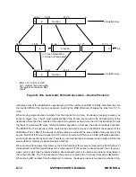
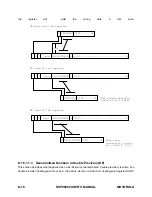
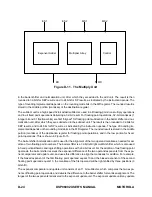
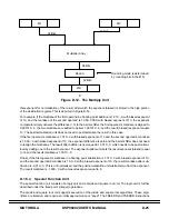
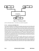
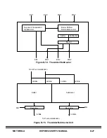
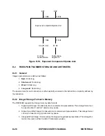
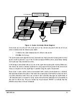
Figure D-13. The Exponent Adder
M1
M2
ED
D
11 Bits
11 Bits
11 Bits
Add exponents
and subtract bias
S1
S2
provide an initial approximation to 1/x and sqrt(1/x), as is described in Appendix A.
D.1.5.5
Controller and Arbtrator Unit
The controller and arbitrator (CA) unit supplies control signals to the processing units of the data ALU and
register file, and is responsible for the full implementation of the IEEE standard. Its operation is determined
by the flush-to-zero (FZ) bit in the status register (SR), which determines whether or not denormalized num-
bers are treated as defined by the standard. In the flush-to-zero mode, all denormalized input operands are
treated as zeros (although their original contents are preserved), and denormalized results are set equal to
zero ("flushed-to-zero"). In the flush-to-zero mode, no additional cycles are required for the normalization of
denormalized numbers as they are treated as zeros. In the IEEE mode, the standard for treatment of de-
normalized numbers is correctly and fully implemented. However, operations on denormalized numbers can
not be performed in a single instruction cycle, except for operations done in the floating point adder when
the operand is a denormalized number in SEP. The controller and arbitrator is responsible for providing the
correct sequence that deals with such situations.
When denormalized numbers are detected as input operands in IEEE mode, the CA unit adds one extra
cycle for entering the IEEE mode procedure. Next, one additional cycle is added for each denormalized in-
put operand. These cycles are used to normalize the input operand. The original value of the operand in the
source register is not affected. During the IEEE mode procedure all activity of the chip is suspended until
the input operands have been normalized. When denormalized output results are detected, the IEEE mode
procedure is entered (one additional instruction cycle) and each result is again normalized (another cycle).
Summary of Contents for DSP96002
Page 3: ...1 2 DSP96002 USER S MANUAL MOTOROLA ...
Page 38: ...MOTOROLA DSP96002 USER S MANUAL 3 15 Figure 3 4 Modulo Arithmetic Unit Block Diagram ...
Page 39: ...3 16 DSP96002 USER S MANUAL MOTOROLA ...
Page 53: ...4 14 DSP96002 USER S MANUAL MOTOROLA ...
Page 76: ...MOTOROLA DSP96002 USER S MANUAL 5 23 Figure 5 8 Address Modifier Summary ...
Page 86: ...6 10 DSP96002 USER S MANUAL MOTOROLA ...
Page 101: ...MOTOROLA DSP96002 USER S MANUAL 7 15 Figure 7 9 HI Block Diagram One Port ...
Page 140: ...7 54 DSP96002 USER S MANUAL MOTOROLA ...
Page 166: ...9 10 DSP96002 USER S MANUAL MOTOROLA ...
Page 181: ...MOTOROLA DSP96002 USER S MANUAL 10 15 Figure 10 8 Program Address Bus FIFO ...
Page 337: ...MOTOROLA DSP96002 USER S MANUAL A 149 ...
Page 404: ...A 216 DSP96002 USER S MANUAL MOTOROLA PC xxxx D ...
Page 460: ...A 272 DSP96002 USER S MANUAL MOTOROLA SIOP Not affected ...
Page 484: ...A 296 DSP96002 USER S MANUAL MOTOROLA SSH PC SSL SR SP 1 SP ...
Page 519: ...MOTOROLA DSP96002 USER S MANUAL A 331 ...
Page 718: ...MOTOROLA DSP96002 USER S MANUAL B 199 ...
Page 871: ... MOTOROLA INC 1994 MOTOROLA TECHNICAL DATA SEMICONDUCTOR M Addendum ...
Page 888: ...MOTOROLA INDEX 1 INDEX ...
Page 889: ......

