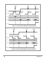
34
MOTOROLA
6.2.6
Timer Status (TS) Bit 24
When the TS bit is set, it indicates that the counter has been decremented to zero.
The TS bit is cleared when the TCSR is read. The bit is also cleared when the timer inter-
rupt is serviced (timer interrupt acknowledge). TS is cleared by hardware and software
resets.
6.2.7
Direction (DIR) Bit 23
The DIR bit determines the behavior of the TIO pin when TIO acts as general purpose IO.
When DIR=0, the TIO pin acts as an input. When DIR=1, the TIO pin acts as an output.
DIR is cleared by hardware and software resets.
Note: The TIO pin can act as a general purpose IO pin only when TC2-TC0 are all zero
and the GPIO bit is set. If one of TC2, TC1, or TC0 is not 0, the GPIO function is disabled
and the DIR bit has no effect.
6.2.8
Data Input (DI) Bit 22
When the TIO pin acts as a general purpose IO input pin (TC2-TC0 are all zero and
DIR=0), the contents of the DI bit will reflect the value the TIO pin. However, if the INV bit
is set, the data in DI will be inverted. When GPIO mode is disabled or it is enabled in out-
put mode (DIR=1), the DI bit reflects the value of the TIO pin, again depending on the
status of the INV bit. DI is set by hardware and software resets.
6.2.9
Data Output (DO) Bit 21
When the TIO pin acts as a general purpose IO output pin (TC2-TC0 are all zero and
DIR=1), writing to the DO bit writes the data to the TIO pin. However, if the INV bit is set,
the data written to the TIO pin will be inverted. When GPIO mode is disabled, writing to
the DO bit will have no effect. DO is cleared by hardware and software resets.
6.2.10
TCSR Reserved bits (Bits 20-0)
These reserved bits are read as zero and should be written with zero for future
compatibility.
6.3
TIMER COUNT REGISTER (TCR)
The 32-bit read-write TCR contains the value (specified by the user program) to be loaded
into the counter when the timer is enabled (TE=1), or when the counter has been decre-
mented to zero and a new event occurs. If the TCR is loaded with n, the counter will be
reloaded after (n+1) events.
If the timer is disabled (TE=0) and the user program writes to the TCR, the value is stored
there but will not be loaded into the counter until the timer becomes enabled. When the
timer is enabled (TE=1) and the user program writes to the TCR, the value is stored there
and will be loaded into the counter after the counter has been decremented to zero and a
new event occurs.
Summary of Contents for DSP96002
Page 3: ...1 2 DSP96002 USER S MANUAL MOTOROLA ...
Page 38: ...MOTOROLA DSP96002 USER S MANUAL 3 15 Figure 3 4 Modulo Arithmetic Unit Block Diagram ...
Page 39: ...3 16 DSP96002 USER S MANUAL MOTOROLA ...
Page 53: ...4 14 DSP96002 USER S MANUAL MOTOROLA ...
Page 76: ...MOTOROLA DSP96002 USER S MANUAL 5 23 Figure 5 8 Address Modifier Summary ...
Page 86: ...6 10 DSP96002 USER S MANUAL MOTOROLA ...
Page 101: ...MOTOROLA DSP96002 USER S MANUAL 7 15 Figure 7 9 HI Block Diagram One Port ...
Page 140: ...7 54 DSP96002 USER S MANUAL MOTOROLA ...
Page 166: ...9 10 DSP96002 USER S MANUAL MOTOROLA ...
Page 181: ...MOTOROLA DSP96002 USER S MANUAL 10 15 Figure 10 8 Program Address Bus FIFO ...
Page 337: ...MOTOROLA DSP96002 USER S MANUAL A 149 ...
Page 404: ...A 216 DSP96002 USER S MANUAL MOTOROLA PC xxxx D ...
Page 460: ...A 272 DSP96002 USER S MANUAL MOTOROLA SIOP Not affected ...
Page 484: ...A 296 DSP96002 USER S MANUAL MOTOROLA SSH PC SSL SR SP 1 SP ...
Page 519: ...MOTOROLA DSP96002 USER S MANUAL A 331 ...
Page 718: ...MOTOROLA DSP96002 USER S MANUAL B 199 ...
Page 871: ... MOTOROLA INC 1994 MOTOROLA TECHNICAL DATA SEMICONDUCTOR M Addendum ...
Page 888: ...MOTOROLA INDEX 1 INDEX ...
Page 889: ......


