background image

30     MW800 CPU Owner’s Manual                                                                                                                                                                                               


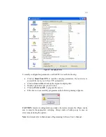
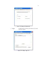
Figure 12. EC Loader Setup 


• 

Click  on  Start  Programming  button  to  begin  programming.  EC 
Programming dialog appears; the progress bar will show programming status. 


Figure 13. EC Loader Programming 


• 

Wait  for  completion  of  programming  process.  When  completed  EC  Flash 
Programming has passed successfully
 will appear. 


Summary of Contents for F5207A, F5217A

Page 1: ...Mobile Workstation 800 Series Model F5207A F5217A Central Processor Unit CPU Box Owner s Manual 6802976C60 O ...

Page 2: ...rt of this manual may be transmitted stored in a retrieval system or translated into any language or computer language in any form or by any means without the prior written permission of Motorola Inc TRADEMARKS Motorola and the Stylized M logo Private DataTAC iDEN are registered trademarks of Motorola Inc Microsoft Windows and the Windows logo are registered trademarks of Microsoft Corporation Int...

Page 3: ...s 18 Section 4 CPU Software 20 CPU Manager 20 MW800 Display Utilities 24 Calibration 24 ExtraKey Application 25 Display Tester 26 Volume Bar 26 Section 5 Software Firmware Upgrade 27 Description Tutorial 27 OS and Drivers 27 Firmware Updates 28 Manual BIOS Update 28 Embedded CPU Firmware 29 Applications 31 Manual CPU Manager Update 32 Manual Display Utilities Update 32 Section 6 Recovery of pre in...

Page 4: ...21 Figure 6 CPU Manager Temperature Tab 22 Figure 7 CPU Manager Notifications Tab 23 Figure 8 CPU Manager Logger Tab 23 Figure 9 Calibration Window 24 Figure 10 ExtraKey Configuration 25 Figure 11 Support Kit Main Menu 27 Figure 12 EC Loader Setup 30 Figure 13 EC Loader Programming 30 Figure 14 Successful Programming 31 Figure 15 Graphics Controller Properties Extreme Driver 55 Figure 16 Display P...

Page 5: ...components CPU box Display and Keyboard This manual only deals with the CPU box which is also referred to as either device or CPU in this manual This manual is organized as follows Section 1 provides an overview Section 2 provides a description of basic operations Section 3 describes various parameters that define CPU configuration when you turn on your computer Section 4 describes a variety of so...

Page 6: ...This manual is designed to supplement the on line help or on line context sensitive help installed with every software component Please review this information to ensure proper use of the product Also if you need to be able to change the configuration of your device refer to Mobile Workstation 800 Series Maintenance Programming Software User s Manual 6802976C70 For additional information visit the...

Page 7: ...attention CAUTION Alerts you of conditions which can result in loss or corruption of data or damage to device DANGER Indicates a potentially hazardous situation which if not avoided may result in injury It may also be used to alert against unsafe practices and property damage only accident hazards ...

Page 8: ...ckoning intelligence on data coming from the GPS receiver This manual covers both CPU models which share many of the same hardware software and mechanical aspects A summary of differences is shown in Appendix I The CPU box provides a wide range of internal and external interfaces USB 2 0 Ethernet RS 232 Firewire for connection to variety of peripherals A PC Card slot situated at the front panel ex...

Page 9: ...setting is NONE press the Power button on the front panel of the CPU box If the CPU box power is connected through the ignition and configured to be turned on off by both the ignition switch and the power button see section 3 Ignition boot up preference setting is POWER ON insert the car key into the ignition switch and rotate it to ACC position or press the Power button on the front panel of the ...

Page 10: ...er optimization parameter in section 3 please wait until this process is completed NOTE If the power source is a 9VDC car battery see Power source parameter in section 3 the device will not power up when the temperature range is below the low operational limit High Temperature Conditions The device will be turned on only if an ambient temperature does not exceed the high operational limit NOTE In ...

Page 11: ...t Windows down and power off If the system does not respond you can turn the device off by pressing and holding the power button for 6 seconds or more To permit this option Critical turn off parameter see Section 3 setting should be ENABLE CAUTION This method of hardware power off may damage your hard disk Extreme Shut Down Certain extreme events may cause you device to power off including ambient...

Page 12: ...ttery voltage drops below the 8 8V limit for 20 seconds or more the device will execute critical shut off and power itself off Power Management This chapter describes low power mode standby and resume normal operating mode In low power state the CPU enters a power saving mode turns off the display backlight and slows down the CPU speed the internal radios remain powered on To resume normal operati...

Page 13: ... help file attached to the Properties of the device A Network Ethernet device can resume the CPU from standby if its setting specifies the operating system to do so To enable this feature Allow this device to bring the computer out of standby option Power Management tab in Properties should be selected For details about this option refer to the help file attached to the Properties of the device Pr...

Page 14: ... Owner s Manual CAUTION If the system does not respond you can turn the device off by pressing and holding the power button for 6 seconds or more Be aware this method of hardware power off may damage your hard disk ...

Page 15: ...enables or disables this feature Factory setting is ENABLE Critical turn off Normally if the system does not respond you can turn the device off by pressing and holding the power button for 6 seconds or more This parameter enables or disables this feature Factory setting is ENABLE Power button preference Normally you can turn the device on and off by pressing the power button This parameter enable...

Page 16: ...ns internal mini PCI wireless LAN adapter on and off Factory setting is ON Radio status on power up Selects the initial state of the internal WAN GPRS iDEN or Private DataTAC radio Factory setting is ON Main radio power switch The internal radio is connected to or disconnected from a power source This parameter turns the radio power switch on and off Factory setting is ON GPO0 state on power up De...

Page 17: ...ice is fitted with an internal iDEN modem It turns on or off a special programming mode of the iDEN modem Factory setting is OFF SB9600 mode This parameter is pertinent if the device is fitted with an internal iDEN modem and allows a data in SB9600 format to be encapsulated Factory setting is ON Heater optimization The CPU has internal hard disk heater which allows operating in low temperatures Th...

Page 18: ...in Appendix J CPU Configuration Change This chapter describes software tools and the most common methods to change CPU configuration Maintenance Programming Software The Maintenance Programming Software enables modification of the configuration that starts when you turn the CPU on Use the MPS context sensitive on line help information for assistance in configuring the device How to Modify Configur...

Page 19: ...ackup the original codeplug data Modify a parameter per your selection Click on Write to CPU to program the device If the device is successfully programmed the following message appears CAUTION Incorrect configuration can make the device inoperable Please make sure to acquire the appropriate codeplug Always make a backup copy in case an error is made during the update Note For details refer to Mai...

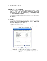
Page 20: ...pplications refer to the help file attached to each application CPU Manager This software application provides basic information about the CPU unit and selection of desired notifications in extreme conditions To run CPU Manager click MW800 CPU Manager icon from the Start menu This application provides the following Versions General information about CPU hardware embedded firmware and CPU software ...

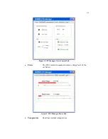
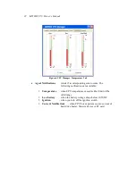
Page 21: ...21 Figure 4 CPU Manager Lines Control Tab Power The CPU current consumption and a voltage level of the car battery Figure 5 CPU Manager Power Tab Temperature Real time internal temperatures ...

Page 22: ...The following notifications are available Temperature when CPU temperature exceeds either limit of the valid range Low battery when the battery voltage drops below 10 5VDC Ignition when you turn off the ignition switch Current Notifications when CPU box experiences over current of hard drive heater firewire device or PC card ...

Page 23: ...23 Figure 7 CPU Manager Notifications Tab Logger Troubleshooting tool allowing documentation of extreme events into a log file Figure 8 CPU Manager Logger Tab ...

Page 24: ...or there may be minor variations between corresponding data points due to resistance variance of each panel When you use touch panel module for the first time or when there is discrepancy between the touched and displayed positions calibration is required This needs to be done only once whereupon the calibration data is stored The CPU will automatically calculate the touched position on display mo...

Page 25: ...left clicking the ExtraKey tray icon and choosing Configuration in the pop up menu Each display function key can be mapped either to a hot key such as Ctrl X F1 etc to a file as a shortcut or to the display switch Figure 10 ExtraKey Configuration How to set a shortcut to the hot key Choose Hot Key in the Map to drop list Move the cursor to Press new hotkey field and right click once to activate it...

Page 26: ...ase read this information to ensure proper operation of the device Display Tester This tool is simple test application for troubleshooting certain display features This tool is for display diagnostics purposes only Volume Bar This application sets the volume level The Volume window allows color modifications and pops up on every volume change If your display unit includes the BlueTooth feature thi...

Page 27: ... when you installing or updating unique software and firmware components in your device Description Tutorial Insert the MW800 Support CD into the CD drive The Main Menu screen automatically appears as shown Figure 11 Support Kit Main Menu To perform the desired action click on the particular option and follow the on screen instructions to continue and complete the process OS and Drivers Insert the...

Page 28: ... in your device Video Capture Updates Conexant video capturing driver Windows SP Updates Windows XP Service Pack 2 and Windows 2000 Service Pack 4 accordingly to the installed Operation System Firmware Updates Insert the Support Kit into the CD ROM drive and click on the Firmware Updates button The MW800 Support Kit provides automatic upgrading of the following unique firmware components BIOS Upda...

Page 29: ...ge displays asking for confirmation to continue You can continue or cancel Press OK on the confirmation box to start the procedures you selected Reboot your device when the procedure is completed Note do not interrupt the program before task completes Embedded CPU Firmware For manual CPU firmware update launch the MPS and then the EC Loader tool This tool provides the ability to program a S Record...

Page 30: ...art Programming button to begin programming EC Programming dialog appears the progress bar will show programming status Figure 13 EC Loader Programming Wait for completion of programming process When completed EC Flash Programming has passed successfully will appear ...

Page 31: ...pplication communicates with the radio unit and provides a GUI interface of the radio control head allowing full control of the radio via the display touch panel Bluetooth Package Installs or updates the BluePC Bluetooth stack driver solution to enable a wireless connection between the MW800 and other Bluetooth devices WM Capture Installs or updates the Windows Media WM Capture 9 Series tool allow...

Page 32: ...s select MW800 CPU Manager and click Change Remove button Install the current version of CPU Manager Double click on the icon of new version of MW800 CPU Manager and follow on screen instructions Manual Display Utilities Update You can manually update the Display Utilities in your device as follows Remove the current version of MW800 Display utilities Go to Control Panel Add and Remove Programs se...

Page 33: ...ng Windows 2000 you can fix the problem by using the ConfigSafe program To access ConfigSafe program click Start Programs ConfigSafe ConfigSafe In Windows XP System Restore tool might fix the problem and revert the system settings and registry entries to an earlier state To access System Restore tools click Start All Programs Accessories System Tools System Restore Recovering applications If you h...

Page 34: ...he first boot priority for USB device and exit from BIOS setting with configuration save and reboot Follow the instructions on the screen Press the Y key when Copy disk image from CD to hard disk Continue appears on the screen Type the word agree and press Enter when This will erase all data type agree to confirm this action appears on the screen Wait until copying is finished Disconnect the USB d...

Page 35: ...800 The address for MW800 home page is http www motorola com This site includes general information about the device as well as answers to questions regarding operational issues with the MW800 The site also provides the following Recent software application updates Updated embedded firmware for your computer The latest device drivers ...

Page 36: ...ctric current in power and communication cables is hazardous To prevent shock hazard follow the installation methods recommended in the Installation Manual DANGER An improperly grounded device is hazardous To prevent shock hazard follow the installation methods recommended in the Installation Manual CAUTION The device dissipates heat during normal operation When the device is operating do not allo...

Page 37: ...ting any card into PC card slots at an angle it could damage connectors in the device CAUTION Normally if the system does not respond you can turn the device off by pressing and holding the power button for 6 seconds or more Be aware this method of hardware power off may damage the hard disk CAUTION Do not insert or remove a PC card when the MW800 is in Standby mode Before you insert or remove a c...

Page 38: ...xtended by Motorola to the original end user purchaser purchasing the Product for purposes of leasing or for commercial industrial or governmental use only and is not assignable or transferable to any other party This is the complete warranty for the Product manufactured by Motorola Motorola assumes no obligations or liability for additions or modifications to this warranty unless made in writing ...

Page 39: ... with Motorola s normal warranty inspection and testing of the Product to verify any warranty claim F Product which has had the serial number removed or made illegible G Batteries they carry their own separate limited warranty H Freight costs to the repair depot I A Product which due to illegal or unauthorized alteration of the software firmware in the Product does not function in accordance with ...

Page 40: ...la will have no liability with respect to any claim of patent infringement which is based upon the combination of the Product or its parts furnished hereunder with software apparatus or devices not furnished by Motorola nor will Motorola have any liability for the use of ancillary equipment or software not furnished by Motorola which is attached to or used in connection with the Product The forego...

Page 41: ...Emission EME safety leaflet Motorola publication number 68P02967C16 FCC Compliance Notice The FCC requires that manuals pertaining to Class A and Class B computing devices must contain warnings about possible interference with local residential radio and TV reception This warning reads as follows NOTE This equipment has been tested and found to comply with limits for a Class B digital device pursu...

Page 42: ...D 810F method 506 4 Procedure III Dust Blowing 5 hours in dust 140 mesh silica flour laden atmosphere dust agitation time is for 2 seconds every 15 minutes Salt Fog 8 hours 5 Sodium Chloride at 35 C after exposure per MIL STD 810F 505 4 Procedure I Flammability Per UL94 HB Solar Radiation 7 cycles of 24 hours with no functional degradation per MIL STD 810F 505 4 Procedure I Shock Crash Hazard 75 g...

Page 43: ...0 05 A Capability to support 9 VDC vehicle battery Vehicle ignition switch sensing Electrical Transients meet ISO7637 1 standard Car battery 1A maximum and 5 VDC 1A maximum power outputs to peripherals from AUX port Features Operating System Windows XP Pro or Windows 2000 Basic Processor see Appendix G for additional options Intel Pentium M 715 1 5 GHz processor Memory see Appendix G for additiona...

Page 44: ...us Two speakers on the front of the display panel one speaker in 8 4 model Two USB 1 1 connectors second USB port is optional in 8 4 8 function soft key buttons 6 in 8 4 Volume brightness standby and backlight control buttons On Screen Display Emergency button Workstation power button Video controller Integrated 2D or 3D graphic and multimedia accelerator External CPU Interfaces 2 USB 2 0 connecto...

Page 45: ...5 Auxiliary Port Ignition Sense 4 TTL level I O ports two inputs and two outputs Car battery and 5VDC power outputs 1A max Standard USB 2 0 port F5207A only Vehicle speed and direction inputs F5217A only ...

Page 46: ...TAL AUDIO Green 8 IGNITION IN Blue 9 BOOTBLOCK IN Violet 10 PROG ENTER AUX IN Gray 11 GND Red 12 MICNEG OUT AUDIO Orange 13 VREF MIC OUT AUDIO Yellow 14 V12 OUT OUT Car battery Green 15 V12 OUT OUT Car battery White 16 GPI0 IN GPIO Pink 17 GPI1 IN GPIO Light Green 18 GPO0 OUT GPIO Black White 19 GPO1 OUT GPIO Brown White 20 1W I O Red White 21 DSC EN RADIO Orange White 22 DSC UPLINK RADIO Green Wh...

Page 47: ...ow 14 V12 OUT OUT Car battery Green 15 V12 OUT OUT Car battery White 16 GPI0 IN GPIO Pink 17 GPI1 IN GPIO Light Green 18 GPO0 OUT GPIO Black White 19 GPO1 OUT GPIO Brown White 20 1W I O Red White 21 DSC EN RADIO Orange White 22 DSC UPLINK RADIO Green White 23 DSC DOWNLINK RADIO Blue White 24 GND Blue 25 V5 OUT OUT 5VDC Violet 26 V5 OUT OUT 5VDC ...

Page 48: ...1 Primary Display 1 6FT 0 5M DISPLAY CPU V306 4 5FT 1 4M DISPLAY CPU V591 9 6FT 2 9M DISPLAY CPU V75 12FT 3 6M DISPLAY CPU V65 17FT 5 2M DISPLAY CPU V648 Cables for 8 4 Primary Display 12FT 3 6M CPU TO 8 4 DISPLAY VA00073 16FT 5 0M CPU TO 8 4 DISPLAY VA00074 Additional Interface Cables 1 6FT 0 5M STD PC TO MW800 DISPLAY VA00046 1 6FT 0 5M MW800 TO STD SCREEN V649 FILTER LINE CABLE CE MW800 V259 Dr...

Page 49: ... CABLE FKN8143 17FT 5 2M DISPLAY CPU CABLE FKN8070 Cables for 8 4 Primary Display 11 5FT 3 5M CPU TO 8 4 DISPLAY FKN8216 16FT 5 0M CPU TO 8 4 DISPLAY FKN8217 Additional Interface Cables LINE OUT CABLE ADAPTOR MW800 FKN8081 1 6FT 0 5M MW800 TO STANDARD SCREEN CABLE FKN8144 1 6FT 0 5M STD PC TO MW800 DISPLAY CBL FKN8090 15AMP POWER CBL FKN4711 FILTER LINE CABLE CE MW800 FKN8179 EXT SPEAKER CABLE ADA...

Page 50: ...50 MW800 CPU Owner s Manual Speaker EXTERNAL SPEAKER FHN1669 Converter CONVERTER USB TO 4 RS232 FLN2955 ...

Page 51: ...utdown timer 3 min Heater optimization 0ºF Radio status on power up ON Main radio power switch ON Radio ring indicator RI ENABLE System ring indicator RI mask DISABLE IDEN programming mode OFF SB9600 mode OFF GPO0 state on power up OFF GPO1 state on power up OFF GPS state on power up OFF GPS mode TSIP Trimble GPS receiver NMEA u Blox GPS receiver Auxiliary 5V output ENABLE Auxiliary 12V output ENA...

Page 52: ...rts Firewire connectors 1 Firewire port IEEE1394 standard Not supported Display 2 connector Carries DVI for flat screen interface also carries RGB USB and audio to the screen with additional cable adapters optional Not supported AUX connector Provide additional USB 2 0 port Provides vehicle speed and direction inputs Internal Interface Embedded Controller Connected via serial COM4 port Connected v...

Page 53: ...creen DISABLED Summary screen DISABLED BIOS Version System Memory Extended Memory Security Supervisor password is CLEAR User password is CLEAR Set supervisor password hit Enter and type your supervisor password Set user password not available Diskette access SUPERVISOR Fixed disk boot sector NORMAL Password on boot DISABLED Virus check reminder DISABLED System backup reminder DISABLED ...

Page 54: ...2000 include Intel s Embedded video driver in the Driver folder at the disk D If you need using the RGB display as the primary and the secondary monitors please do the following Open Embedded Driver folder at the disk D Double click on Setup Follow to on screen instructions until the installation is completed Extreme Graphics Click the Start menu and select Control Panel Click Appearance and Theme...

Page 55: ...ded Display Multi monitor allowing a large Windows desktop that spans two displays and creates more screen real estate than a single display provides Applications can be moved from one monitor to another or can be on more than one monitor simultaneously See the Intel Extreme Graphics Driver User s Guide for more information Embedded Driver Click the Start menu and select Control Panel Click Appear...

Page 56: ...an extend your display to allow a large Windows desktop that spans two displays as the following Drag the second monitor icon Check Extend my Windows desktop onto this monitor and the click the Apply or OK button Applications can be moved from one monitor to another or can be on more than one monitor simultaneously To configure the second monitor graphics mode click Advanced to open the Properties...

Page 57: ...ven by same set of timings Both displays should support the same resolution and refresh rate See the Intel Embedded Graphics Driver User s Guide for more information NOTES It is recommended to disable touch screen of the secondary display in the Device Manager Mouse folders HID mouse The Bluetooth module must be installed in the primary display During the boot up a time between powering the MW800 ...

Page 58: ...58 MW800 CPU Owner s Manual Both displays should be set to the same resolution ...

Page 59: ...The internal temperature is higher than the valid limit Please save your work before shutting down Never turn on the device until it cools down to normal operating temperature Warning condition is over Cancel Warning MW800 CPU temperature is low The system will shutdown in 3 minutes The internal temperature is below of the valid limit Please save your work before shutting down Never turn on the de...

Page 60: ... valid input signal from CPU box Check the plugs and CPU cable The following table describes CPU failures without a user notification Table 8 Failures Without Notification Problem Do the following Cannot turn the device off the system does not respond Turn off the device by pressing and holding the power button for 6 seconds or more Use either CPU or display power buttons If the device is still no...

Page 61: ...al Purpose Input GPO General Purpose Output GPRS General Packet Radio Service GPS Global Positioning System iDEN Integrated Digital Enhanced Network IEEE Institute of Electrical and Electronic Engineers I O Input Output LAN Local Area Network LCD Liquid Crystal Display MPS Maintenance Programming Software MW Mobile Workstation NIT Near Infrared Transmission NMEA National Marine Electronics Associa...

Page 62: ...ocol TTL Transistor Transistor Logic UHF Ultra High Frequency UL Underwriters Laboratories USB Universal Serial Bus VCR Videocassette Recorder VDC Volts Direct Current WWAN Wireless Wide Area Network WLAN Wireless Local Area Network XGA eXtended Video Graphics Array ...

Reviews: