7-8
Theory of Operation
Controller Detailed
Functional Description
General
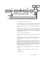
The radio controller consists of four main subsections:
•
Digital Control
•
Audio Processing
•
Power Control
•
Voltage Regulation
The digital section consists of a microprocessor, memory ICs, glue logic circuitry,
signal MUX ICs, On/Off circuit, and general purpose Input/Output circuitry.
The controller is based on the Motorola 68HC11K1 microprocessor (U0101), 8-
Kbyte SRAM (U0103), 128 Kbyte-OTP memory (U0102), and 4 Kbyte EEPROM
(U0104).
Note:
From this point on, the 68HC11K1 microprocessor will be
referred to as K1
µ
P or
µ
P.
References to a Control Head will be to type P+ (Display
radio).
Voltage Regulators
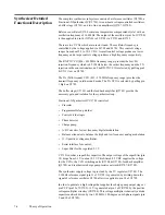
Voltage regulation for the controller is provided by 3 separate devices; U0631
(LP2951CM) +5V, U0601 (LM2941T) +9.3V, and UNSW 5V (R0621 and
VR0621). An additional regulator is located in the RF section.
5-V voltage regulation for the digital circuitry is provided by U0631. Input and
output capacitors (C0631/0632 and C0633-0635) are used to reduce high-
frequency noise and provide proper operation during short battery transients. This
regulator provides a reset output (pin 5) that drops to 0 V while the regulator
output goes out of regulation. This is used to reset the controller in order to prevent
improper operation. Diode D0631 prevents discharge of C0632 by negative spikes
on the 9V3 voltage.
Regulator U0601 is used to generate the 9.3 V required by some audio circuits, the
RF circuitry and power control circuitry. Input and output capacitors (C0601-0603
and C0604/0605) are used to reduce high-frequency noise. R0602/R0603 set the
regulator output voltage. If the voltage at pin 1 is greater than 1.3 volts the
regulator output decreases and if the voltage is less than 1.3 V, the regulator output
increases. This regulator output is electronically disabled by a 0 V signal on pin 2.
Q0601 and associated circuitry (R0601/0604/0605) are used to disable the
regulator when the radio is turned off.
UNSW 5V is only used by a few circuits which draw low current and require 5 V
while the radio is off.
UNSW 5V CL is used to save the internal RAM data. C0622 allows the battery
voltage to be disconnected for a couple of minutes without losing RAM
parameters. Diode D0621 prevents radio circuitry from discharging this capacitor.
The SW +B voltage is monitored by the
µ
P through voltage divider R0641/R0642.
Diode VR0641 limits the divided voltage to 5.1 V in order to protect the
µ
P.


