5-2
Schematic Diagrams, Overlays, and Parts Lists
5.2
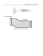
Flex Layout
Figure 5-1. Keypad-Controller Interconnect Flex
LAYER 1 (L1)
LAYER 2 (L2)
LAYER 3 (L3)
LAYER 4 (L4)
LAYER 5 (L5)
LAYER 6 (L6)
INNER LAYERS
SIDE 1
SIDE 2
6-LAYER CIRCUIT
COPPER STEPS IN PROPER
LAYER SEQUENCE
BOARD DETAIL VIEWING
98
C
J200
40
J100
40
<- TO KP
8480475Z02 REV A
TO CTRL ->
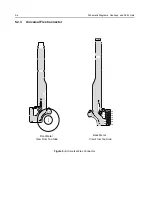
Front Metal
View from Top side
Summary of Contents for HT1250-LS+
Page 10: ...viii ...
Page 12: ...x Product Safety and RF Exposure Compliance ...
Page 16: ...1 4 Introduction ...
Page 58: ...4 22 Maintenance ...
Page 64: ...5 6 Schematic Diagrams Overlays and Parts Lists ...


