2-25
2.8.4
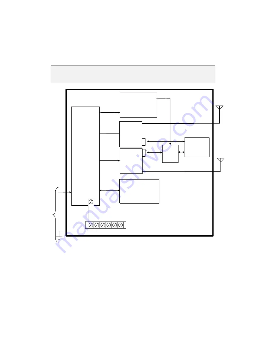
Connecting the RTU by Two Separate Mobile Radios
The following diagram (See Figure
2-22) illustrates the proper connections for
connecting both the CPU Port 2 (Intrac protocol) and Port 3 (MDLC protocol) to
separate Mobile Radios using the 8 Ampere Power Supply.
N
N
o
o
t
t
e
e
:
:
Port 2 (Intrac) is to be connected to the “Low Power” Radio and Port
3 (MDLC) is to be connected to the “High Power” Radio.
VCC
CMU
VCC
CMU
3-Slot Chassis
AC
Input
Antenna
Power
Supply
LOGIC
RADIO
PGND
IN
BATT
Back Up Battery
Radio
(
High Power)
Radio
(
Low Power
)
Jumper Strip
CPU
Module
Port 3
Port 2
Data
Data
Protective Gnd Strip
Power Supply
Module
(Less)
AUX
BAT
PWR
IN
Primary
Power Supply
Radio
Power
Supply
Aux
Power
Supply
AUX
Battery
Power
Supply
Comm
Cable
Adaptor
Antenna
Comm
Cable
Adaptor
8 Ampere
Figure
2-22 Connecting the RTU by two Separate Mobile Radios - Interconnection
Diagram
StockCheck.com


