3-22
3.6.2
Diagnostic LED Panel
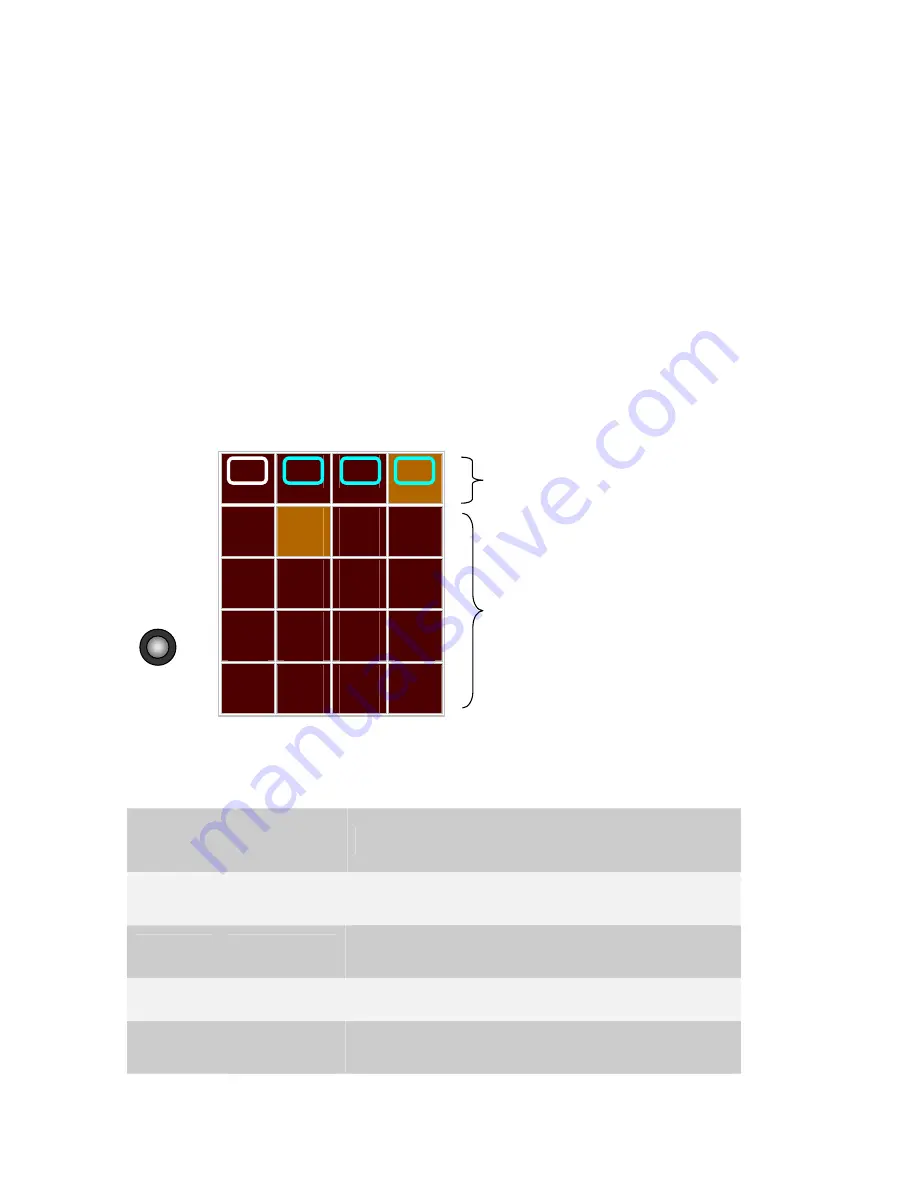
Use the matrix display on the CPU Module for diagnostics and testing of Single Cable
Module (See Figure
3-13). The top row indicates which module (CPU, M1, M2 or M3) the
LED panel is set to display and the blue numerals on the LED panel are the I/O
indications.
Press the pushbutton once, momentarily, to activate the LED panel. Every consecutive
momentary depression of the pushbutton will advance the display to the next module, in
the following order: CPU, M1 (I/O Module 1), M2 (I/O Module 2), and M3 (I/O Module 3).
The next depression of the pushbutton will return the display to the CPU. Verify that the
relevant LED is lit.
For example; Figure
3-13 Single Cable Module LED Display shows indications from the
module in slot number 3 (M3). LED number 5 is on, indicating that at least one of the
connected RTUs is turned on.
3-8 specifies the LED indications for the Single Cable Module.
CPU
M1
M2
M3
LOAD
1
CONF
5
APPL
9
MON
13
RST
2
Tx1
6
Tx2
10
Tx3
14
ERR
3
Rx1
7
Rx2
11
Rx3
15
BAT
4
CM1
8
CM2
12
CM3
16
Figure
3-13 Single Cable Module LED Display
Table
3-8 Single Cable Module - Diagnostic Led Display
LED No.
Indication
Description
1
40V Fail
LED ON if the output voltage of the voltage
converter drops below 33.0 V.
2
Line Sense
LED ON if the line voltage drops below the
predefined threshold.
3
---
Not Used
4
Sequence
Stopped
LED ON when the Single Cable Module enters into
Test Mode and pseudo-random sequence is not
o
u
t
p
u
t
t
e
d
t
o
t
h
e
l
i
n
e
d
r
i
v
e
r
.
t
Slot Number
I/O LEDs (1 to 16)
StockCheck.com


