M68360QUADS-040 Hardware User’s Manual
Hardware Preparation and Installation
15
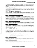
2.4.1
+5V Power Supply Connection
The M68360QUADS-040 re5 Vdc @ 5 A max, power supply for operation. Connect the +5V power
supply to connector P11 as shown below:
FIGURE 2-3 P6: +5V Power Connector
P5 is a 3 terminal block power connector with power plug. The plug is designed to accept 14 to 22 AWG
wires. It is recommended to use 14 to 18 AWG wires. To provide solid ground, two Gnd terminals are
supplied. It is recommended to connect both Gnd wires to the common of the power supply, while VCC is
connected with a single wire.
NOTE
Since hardware applications can be connected to the
M68360QUADS-040 using the expansion connectors P8 and
P10, the additional power consumption should be taken into
consideration when a power supply is connected to the
M68360QUADS-040.
2.4.2
P7: +12V Power Supply Connection
The M68360QUADS-040 re12 Vdc @ 1 A max, power supply for the Ethernet AUI port. The
M68360QUADS-040 can work properly without the +12V power supply, if the AUI port is not in use or if the
AUI port is used with an AUI hub that does not require 12 V to be provided by the network termination
equipment.
Connect the +12V power supply to connector P6 as shown below:
FIGURE 2-4 P6: +12V Power Connector
P6 is a 2 terminal block power connector with power plug. The plug is designed to accept 14 to 22 AWG
wires. It is recommended to use 14 to 18 AWG wires.
2.4.3
ADI Installation
For ADI installation on various host computers, refer to APPENDIX A - on page 51.
2.4.4
Host computer to M68360QUADS-040 Connection
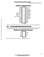
The M68360QUADS-040 ADI interface connector, P1, is a 37 pin, male, D type connector. The connection
between the M68360QUADS-040 and the host computer is by a 37 line flat cable, supplied with the ADI
board. FIGURE 2-5 below shows the pin configuration of the connector.
VCC
Gnd
Gnd
1
2
3
VPP
Gnd
1
2
F
re
e
sc
a
le
S
e
m
ic
o
n
d
u
c
to
r,
I
Freescale Semiconductor, Inc.
For More Information On This Product,
Go to: www.freescale.com
n
c
.
..


