HARDWARE PREPARATION AND INSTALLATION
2-2
M68HC11EVB/D
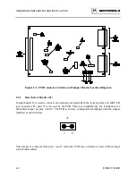
Figure 2-1. EVB Connector, Switch, and Jumper Header Location Diagram
2.3.1
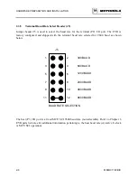
Reset Select Header (J1)
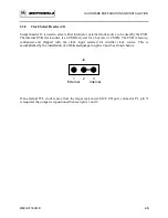
Jumper header J1 is used to connect an external reset signal from the target system (via MCU I/O
port connector P1, pin 17) to be used by the EVB. This is accomplished by the installation of a
fabricated jumper on pins 1 and 2. The EVB is factory-configured and shipped with the jumper
installed as shown below.
J1
1 2
This jumper is removed from pins 1 and 2 when the EVB reset circuitry is used without target
system intervention.
Summary of Contents for M68HC11EVB
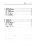
Page 9: ...CONTENTS x M68HC11EVB D ...
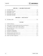
Page 35: ...MONITOR PROGRAM 3 8 M68HC11EVB D ...
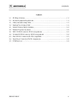
Page 81: ...OPERATING INSTRUCTIONS 4 46 M68HC11EVB D ...
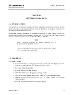
Page 97: ...SUPPORT INFORMATION 6 12 M68HC11EVB D Figure 6 3 EVB Schematic Diagram Sheet 2 of 2 ...
Page 103: ...APPLICATIONS B 2 M68HC11EVB D Figure B 1 Single Chip Mode Configuration ...


