MONITOR PROGRAM
M68HC11EVB/D
3-5
5
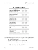
When accessing BUFFALO utility routines, always reference the routines by the applicable
address ($FF7C through $FFD0) in the jump table rather than the actual address in the
BUFFALO monitor program. Jump table addresses remain the same when a new version of
BUFFALO is developed even though the actual addresses of the routine may change. Programs
that reference routines by the jump table addresses are not required to be changed to operate on
revised versions of the BUFFALO monitor program.
3.2.5
Command Table
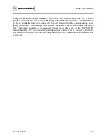
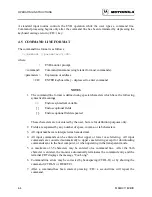
The command table consists of three lines for each entry. The first byte is the number of
characters in the command name. The second entry is the ASCII command name. The third entry
is the starting address of the command module. As an example:
FCB
3
3 characters in command name
FCC
'ASM'
ASCII literal command name string
FDB
#ASM
Jump address for command module
Each command in the BUFFALO program is a individual module. Thus, to add or delete
commands, all that is required is to include a new command module or delete an existing module
and/or delete the entry in the command table.
3.3 INTERRUPT VECTORS
Interrupt vectors residing in MCU internal ROM are accessible as follows. Each vector is
assigned a three byte field residing in EVB memory map locations $0000-$00FF. This is where
the monitor program expects the MCU RAM to reside. Each vector points to a three byte field
which is used as a jump table to the vector service routine. Table 3-2 lists the interrupt vectors
and associated three byte field.
Summary of Contents for M68HC11EVB
Page 9: ...CONTENTS x M68HC11EVB D ...
Page 35: ...MONITOR PROGRAM 3 8 M68HC11EVB D ...
Page 81: ...OPERATING INSTRUCTIONS 4 46 M68HC11EVB D ...
Page 97: ...SUPPORT INFORMATION 6 12 M68HC11EVB D Figure 6 3 EVB Schematic Diagram Sheet 2 of 2 ...
Page 103: ...APPLICATIONS B 2 M68HC11EVB D Figure B 1 Single Chip Mode Configuration ...


