M68ICS08ABUM/D
2-3
CHAPTER 2 – HARDWARE INSTALLATION
•
Jumper on pins 1 and 2
Default. The M68ICS08AB oscillator is selected.
•
Jumper off
Allows using an oscillator on the target system or injecting a different
clock rate at P6 pin 2.
2.3
INSTALLING THE HARDWARE
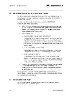
Before beginning, locate these items:
•
9-pin RS-232 serial connector on the board, labeled P2
•
5-volt circular power-input connector on the ABICS
To prepare the ABICS for use with a host PC:
1. Install the MCU into the M68ICS08AB board.
Locate the socket XU1 on the board.
Install the MCU (provided with the ABICS package) into this socket,
observing the pin 1 orientation with the socket’s notch. The top (label
side) of the MCU package must be visible when looking at the
component side of the board.
2. Connect the board to the host PC.
Locate the 9-pin connector labeled P2 on the board. Using the cable
provided, connect it to a serial COM port on the host PC.
3. Apply power to the board.
Connect the 5-volt power supply to the round connector on the board.
Plug the power supply into an AC power outlet, using one of the
country-specific adapters provided. The ICS PWR LED (Yellow) on
the board should light.
2.4
CONNECTING TO A TARGET SYSTEM
The two ways to connect the M68ICS08AB simulator board to a target system
are:
Table 2-3. W5 Configuration Header – Oscillator Source
Pin
Direction
Signal Name
Description
1
out
SP_OSC
4.9152-MHz M68ICS08AB oscillator output
2
in or out
OSC1
OSC1 on sockets and target connectors
Summary of Contents for M68ICS08AB
Page 6: ... 4 CPU32XIPB D ...
Page 8: ... 6 CPU32XIPB D ...
Page 60: ......
Page 61: ......
Page 62: ......
Page 63: ......
Page 64: ......
Page 65: ......
Page 66: ...A 32 M68ICS08ABUM D APPENDIX A TECHNICAL REFERENCE TROUBLESHOOTING ...


