M68ICS08ABUM/D
A-9
APPENDIX A – TECHNICAL REFERENCE & TROUBLESHOOTING
power plug from the ICS08AB. Remove any MCU from sockets
XU1
.
Jumper selections on W4 have no effect when using the MON08 cable.
4. Connect the 16-pin cable from
J3
on the ICS08AB to the target sys-
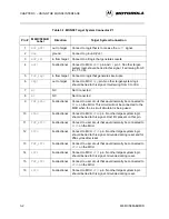
tem’s MON08 connector. Details on designing a MON08 connector for
the target system are given in CHAPTER 3 – USING THE MON08
INTERFACE. If cutable jumpers were used on the target board, the
jumpers must be cut before using the MON08 cable.
5. The target system (including the MCU) must be externally powered.
The target system’s MCU V
DD
must match the
MCU-VDD
setting on
the ICS08AB to communicate with the ICS08AB. If the target system
is not powered by 5 Vdc, connect target system’s Vdd to EVDD input
(
W10
pin 1) on the ICS08AB. The on-board regulator adjust the
MCU-
VDD
to match the Vdd setting on the target system.
6. Exit any ICS08ABZ software that may be running on the host PC. Con-
nect the serial cable between the host PC and the ICS08AB. Apply
power to the ICS08AB by connecting the wall adapter’s output jack to
the ICS08AB. At this point, the
ICS PWR
LED (Green) should be lit,
and the
MCU PWR
LED (Yellow) should be off. If the
MCU PWR
LED
is on, there may be a problem with the host PC’s serial port or the serial
cable. Refer to step 9 for information on host communications.
7. Apply power to the target system. At this point, the target MCU should
be powered. Check for the appropriate voltage at the MCU’s V
DD
pin.
The ICS08AB should leave the target MCU in reset with approximately
0 Vdc at the MCU’s
RST*
pin. Verify this at the target MCU’s
RST*
pin and at
J3
pin 4. If
RST*
floats too high, the MCU may start up and
begin executing code out of its FLASH memory. The ICS08AB should
reset the MCU again in step 8 when the software is started.
8. Start the ICS08ABZ simulator software as described in Section 1.6
HARDWARE QUICK START INSTRUCTIONS while watching
the
MCU PWR
LED.
If the
MCU PWR
LED does not light at all, there may be a problem with
the host PC communicating with the ICS08AB. Continue with step 9.
If the
MCU PWR
LED flickers a few times and then goes out, the host
PC is able to control the ICS08AB but communications may still not be
established with the MCU on the target system. As the flickering of the
MCU PWR
LED indicates, the host PC is applying and removing power
to the ICS08AB board during this period. If the
MCU PWR
LED stays
on, the power is good, but the MCU is not being placed in monitor
mode. Continue with step 9.
Summary of Contents for M68ICS08AB
Page 6: ... 4 CPU32XIPB D ...
Page 8: ... 6 CPU32XIPB D ...
Page 60: ......
Page 61: ......
Page 62: ......
Page 63: ......
Page 64: ......
Page 65: ......
Page 66: ...A 32 M68ICS08ABUM D APPENDIX A TECHNICAL REFERENCE TROUBLESHOOTING ...


