A-4
M68ICS08ABUM/D
APPENDIX A – TECHNICAL REFERENCE & TROUBLESHOOTING
A.3
TROUBLESHOOTING THE QUICK START
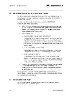
The quick-start installation procedure in section Section 1.6 HARDWARE
QUICK START INSTRUCTIONS describes how to prepare the ICS08AB
for use in the instances where the MCU is installed on the ICS08AB board.
These instances include:
•
Using the ICS08AB as an in-circuit simulator/emulator with a target
cable
•
Using the ICS08AB as a programmer
•
Using the ICS08AB as a stand-alone system without a target board
If you experience difficulties quick starting the kit using the procedure outlined
in Section 1.6 HARDWARE QUICK START INSTRUCTIONS, follow
these steps:
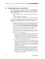
1. Do not use the MON08 cable to a target system in these modes. The
MON08 cable connection is to be used only when the MCU is on the
target system. Troubleshooting information for the MON08 modes may
be found in Section A.4 TROUBLESHOOTING MON08 MODE.
2. Disconnect any target cables from the board. These troubleshooting
steps assume that no target system connections are present.
3. Make sure that the MCU is installed correctly. Insert the MCU with the
orientation notch and pin 1 to the upper left in the respective socket.
4. Make sure the board is getting power:
a. Check the power at the output of the adapter. First disconnect the
ICS08AB from the power supply, then measure the power at the
wall adapter’s output connector to confirm that it produces 5 Vdc.
The outer barrel of the connector is ground, and the inner sleeve is
+5 Vdc. If there is no power at the connector, verify that the adapter
is getting power from the AC power outlet.
b. Check the power at the ICS08AB board. Plug the adapter’s output
connector into the ICS08AB. The
MCU PWR
LED (Yellow) should
light. Check for 5 Vdc at the ICS08AB’s fuse
F1
. If the LED does
not light or if 5 Vdc is not present on fuse
F1
, check the fuse in the
ICS08AB. If more than 6.2 Vdc or reverse voltage is applied to the
ICS08AB, the fuse will blow.
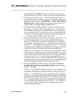
c. Check the ICS08AB MCU PWR. Disconnect the ICS08AB from
the power supply and from the host PC. Configure the ICS08AB
board to the factory defaults. Reconnect the power supply to the
ICS08AB. The
MCU PWR
LED should light. If the LED does not
light, there may be a problem with the ICS08AB causing too much
of a drain on the 5 Vdc supply.
Summary of Contents for M68ICS08AB
Page 6: ... 4 CPU32XIPB D ...
Page 8: ... 6 CPU32XIPB D ...
Page 60: ......
Page 61: ......
Page 62: ......
Page 63: ......
Page 64: ......
Page 65: ......
Page 66: ...A 32 M68ICS08ABUM D APPENDIX A TECHNICAL REFERENCE TROUBLESHOOTING ...


