9- 20
M68020 USER’S MANUAL
MOTOROLA
9.8.2 Module Return
The RTM instruction is used to return from a module. For the type $00 module stack
frame, the processor reloads the condition codes, the PC, and the module data area
pointer register from the frame. The frame is removed from the top of the stack, the
argument count is added to the stack pointer, and execution returns to the calling module.
For the type $01 module stack frame, the processor reads the access level, condition
codes, PC, saved module data area pointer, and saved stack pointer from the module
stack frame. The access level is written to the DAL for validation by external hardware; the
processor then reads the access status to check the validation. If the external hardware
determines that the change in access right should not be granted, the access status is
zero, and the processor takes a format error exception. No visible processor registers are
changed, nor should the current access level enforced by external hardware be changed.
If the external hardware determines that the change in access rights should be granted,
the external hardware changes its access level, the values read from the module stack
frame are loaded into the corresponding processor registers, the argument count is added
to the new stack pointer value, and execution returns to the calling module.
If the called module does not wish the saved module data pointer to be loaded into a
register, the RTM instruction word can select register A7, and the loaded value will be
overwritten with the correct stack pointer value after the module stack frame is
deallocated.
Summary of Contents for MC68020
Page 16: ...9 29 95 SECTION 1 OVERVIEW UM Rev 1 0 xx M68020 USER S MANUAL MOTOROLA ...
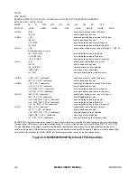
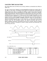
Page 268: ...MOTOROLA M68020 USER S MANUAL 9 13 Figure 9 9 Access Time Computation Diagram ...
Page 286: ...MOTOROLA M68020 USER S MANUAL 10 11 Figure 10 3 Read Cycle Timing Diagram ...
Page 287: ...10 12 M68020 USER S MANUAL MOTOROLA Figure 10 4 Write Cycle Timing Diagram ...
Page 288: ...MOTOROLA M68020 USER S MANUAL 10 13 Figure 10 5 Bus Arbitration Timing Diagram ...


