MOTOROLA
M68020 USER’S MANUAL
10-1
The device contains circuitry to
protect the inputs against damage
due to high static voltages or electric
fields; however, normal precautions
should be taken to avoid application
of voltages higher than maximum-
rated voltages to these high-
impedance circuits. Tying unused
inputs to the appropriate logic
voltage level (e.g., either GND or
VC C ) enhances reliability of
operation.
SECTION 10
ELECTRICAL CHARACTERISTICS
This section provides the thermal characteristics and electrical specifications for the
MC68020/EC020. Note that the thermal and DC electrical characteristics are listed
separately for the MC68020 and the MC68EC020. All other data applies to both the
MC68020 and the MC68EC020 unless otherwise noted.
10.1 MAXIMUM RATINGS
Rating
Symbol
Value
Unit
Supply Voltage
V
CC
–0.3 to +7.0
V
Input Voltage
V
in
–0.5 to +7.0
V
Operating Temperature Range
Minimum Ambient Temperature
Maximum Ambient Temperature
PGA, PPGA, PQFP
Maximum Junction Temperature
CQFP
T
A
T
A
T
J
0
70
110
°
C
°
C
°
C
Storage Temperature Range
T
stg
–55 to 150
°
C
10.2 THERMAL CONSIDERATIONS
The average chip-junction temperature, T
J
, in
°
C can be obtained from:
T
J
= T
A
+ (P
D
•
θ
JA
)
(10-1)
where:
T
A
= Ambient Temperature,
°
C
θ
JA
= Package Thermal Resistance, Junction-to-Ambient,
°
C/W
P
D
= P
INT
+ P
I/O
P
INT
= I
CC
X
V
CC
, Watts—Chip Internal Power
P
I/O
= Power Dissipation on Input and Output Pins—User Determined
For most applications, P
I/O
< P
INT
and can be neglected.
An approximate relationship between P
D
and T
J
(if P
I/O
is neglected) is:
P
D
= K
÷
(T
J
+ 273
°
C)
(10-2)
Summary of Contents for MC68020
Page 16: ...9 29 95 SECTION 1 OVERVIEW UM Rev 1 0 xx M68020 USER S MANUAL MOTOROLA ...
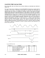
Page 268: ...MOTOROLA M68020 USER S MANUAL 9 13 Figure 9 9 Access Time Computation Diagram ...
Page 286: ...MOTOROLA M68020 USER S MANUAL 10 11 Figure 10 3 Read Cycle Timing Diagram ...
Page 287: ...10 12 M68020 USER S MANUAL MOTOROLA Figure 10 4 Write Cycle Timing Diagram ...
Page 288: ...MOTOROLA M68020 USER S MANUAL 10 13 Figure 10 5 Bus Arbitration Timing Diagram ...


