MOTOROLA
MC68306 USER'S MANUAL
xiii
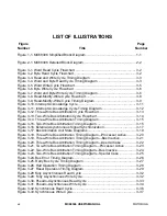
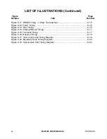
LIST OF ILLUSTRATIONS (Continued)
Figure
Page
Number
Title
Number
Figure 4-1. Programmer's Model ..............................................................................
4-2
Figure 4-2. Status Register .......................................................................................
4-3
Figure 4-3. General Exception Processing Flowchart ..............................................
4-13
Figure 4-4. General Form of Exception Stack Frame ...............................................
4-14
Figure 4-5. Exception Vector Format ........................................................................
4-15
Figure 4-6. Address Translated from 8-Bit Vector Number ......................................
4-15
Figure 4-7. Supervisor Stack Order for Bus or Address Error Exception .................
4-21
Figure 5-1. Chip Select Expansion ...........................................................................
5-12
Figure 5-2. Oscillator Circuit Diagram.......................................................................
5-17
Figure 6-1. Simplified Block Diagram .......................................................................
6-1
Figure 6-2. External and Internal Interface Signals ..................................................
6-5
Figure 6-3. Baud Rate Generator Block Diagram .....................................................
6-7
Figure 6-4. Transmitter and Receiver Functional Diagram .......................................
6-8
Figure 6-5. Transmitter Timing Diagram ...................................................................
6-9
Figure 6-6. Receiver Timing Diagram .......................................................................
6-11
Figure 6-7. Looping Modes Functional Diagram .......................................................
6-14
Figure 6-8. Multidrop Mode Timing Diagram ............................................................
6-15
Figure 6-9. Serial Module Programming Model ........................................................
6-18
Figure 6-10. Serial Module Programming Flowchart ................................................
6-38
Figure 7-1. Test Access Port Block Diagram ............................................................
7-2
Figure 7-2. TAP Controller State Machine ................................................................
7-3
Figure 7-3. Output Cell (O.Cell) ................................................................................
7-7
Figure 7-4. Input Cell (I.Cell) .....................................................................................
7-7
Figure 7-5. Output Control Cell (En.Cell) ..................................................................
7-8
Figure 7-6. Bidirectional Cell (IO.Cell) ......................................................................
7-8
Figure 7-7. Bidirectional Cell (IOx0.Cell)...................................................................
7-9
Figure 7-8. General Arrangement for Bidirectional Pins ...........................................
7-9
Figure 7-9. Bypass Register .....................................................................................
7-11
Figure 8-1. Drive Levels and Test Points for AC Specifications ...............................
8-3
Figure 8-2. Clock Output Timing ...............................................................................
8-4
Figure 8-3. Read Cycle Timing Diagram...................................................................
8-7
Figure 8-4. Write Cycle Timing Diagram ...................................................................
8-8
Figure 8-5. Chip Select and Interrupt Acknowledge Timing Diagram .......................
8-9
Figure 8-6. Bus Arbitration Timing Diagram .............................................................
8-10
Figure 8-7. Bus Arbitration Timing Diagram .............................................................
8-11
Figure 8-8. DRAM Timing – 0-Wait Read, No Refresh .............................................
8-13
Figure 8-9. DRAM Timing – 1-Wait Write, No Refresh .............................................
8-14
Figure 8-10. DRAM Timing – 0- and 1-Wait Refresh ................................................
8-14


