MOTOROLA
MC68306 USER'S MANUAL
6-19
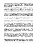
channel A mode register pointer points to DUMR1. The pointer is set to DUMR1 by
RESET
or by a set pointer command, using control register A. After reading or writing
DUMR1A, the pointer points to DUMR2A.
DUMR1A, DUMR1B
7
6
5
4
3
2
1
0
RxRTS
RxIRQ
ERR
PM1
PM0
PT
B/C1
B/C0
RESET:
0
0
0
0
0
0
0
0
Read/Write
RxRTS—Receiver Request-to-Send Control
1 = Upon receipt of a valid start bit,
RTS≈
is negated if the channel's FIFO is full.
RTS≈
is reasserted when the FIFO has an empty position available.
0 = The receiver has no effect on
RTS≈
.
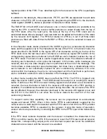
This feature can be used for flow control to prevent overrun in the receiver by using the
RTS≈
output to control the
CTS≈
input of the transmitting device. If both the receiver and
transmitter are programmed for
RTS
control,
RTS
control will be disabled for both since
this configuration is incorrect. See 6.4.1.17 Mode Register 2 for information on
programming the transmitter
RTS≈
control.
RxIRQ—Receiver Interrupt Select
1 = FFULL is the source that generates IRQ.
0 = RxRDY is the source that generates IRQ.
ERR—Error Mode
This bit controls the meaning of the three FIFO status bits (RB, FE, and PE) in the
DUSR for the channel.
1 = Block mode—The values in the channel DUSR are the accumulation (i.e., the
logical OR) of the status for all characters coming to the top of the FIFO since the
last reset error status command for the channel was issued. Refer to 6.4.1.5
Command Register (DUCR) for more information on serial module commands.
0 = Character mode—The values in the channel DUSR reflect the status of the
character at the top of the FIFO.
NOTE
ERR = 0 must be used to get the correct A/D flag information
when in multidrop mode.
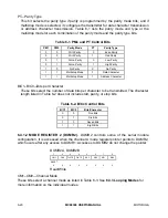
PM1–PM0—Parity Mode
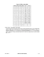
These bits encode the type of parity used for the channel (see Table 6-1). The parity bit
is added to the transmitted character, and the receiver performs a parity check on
incoming data. These bits can alternatively select multidrop mode for the channel.


