6- 20
MC68306 USER'S MANUAL
MOTOROLA
PT—Parity Type
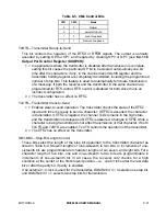
This bit selects the parity type if parity is programmed by the parity mode bits, and if
multidrop mode is selected, it configures the transmitter for data character transmission
or address character transmission. Table 6-1 lists the parity mode and type or the
multidrop mode for each combination of the parity mode and the parity type bits.
Table 6-1. PMx and PT Control Bits
PM1
PM0
Parity Mode
PT
Parity Type
0
0
With Parity
0
Even Parity
0
0
With Parity
1
Odd Parity
0
1
Force Parity
0
Low Parity
0
1
Force Parity
1
High Parity
1
0
No Parity
X
No Parity
1
1
Multidrop Mode
0
Data Character
1
1
Multidrop Mode
1
Address Character
B/C1–B/C0—Bits per Character
These bits select the number of data bits per character to be transmitted. The character
length listed in Table 6-2 does not include start, parity, or stop bits.
Table 6-2. B/Cx Control Bits
B/C1
B/C0
Bits/Character
0
0
Five Bits
0
1
Six Bits
1
0
Seven Bits
1
1
Eight Bits
6.4.1.2 MODE REGISTER 2 (DUMR2). DUMR2 controls some of the serial module
configuration. It is accessed when the channel A mode register pointer points to DUMR2,
which ocurs after any access to DUMR1. Accesses to DUMR2 do not change the pointer.
DUMR2A, DUMR2B
7
6
5
4
3
2
1
0
CM1
CM0
TxRTS
TxCTS
SB3
SB2
SB1
SB0
RESET:
0
0
0
0
0
0
0
0
Read/Write
CM1–CM0—Channel Mode
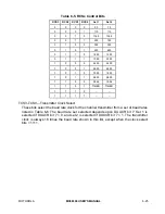
These bits select a channel mode as listed in Table 6-3. See 6.3.3 Looping Modes for
more information on the individual modes.


