6- 34
MC68306 USER'S MANUAL
MOTOROLA
6.4.1.16 INTERRUPT VECTOR REGISTER (DUIVR). The DUIVR contains the 8-bit
vector number of the
IRQ
interrupt.
DUIVR
7
6
5
4
3
2
1
0
IVR7
IVR6
IVR5
IVR4
IVR3
IVR2
IVR1
IVR0
RESET:
0
0
0
0
1
1
1
1
Read /Write
IVR7–IVR0—Interrupt Vector Bits
Each module that generates interrupts can have an interrupt vector field. This 8-bit
number indicates the offset from the base of the vector table where the address of the
exception handler for the specified interrupt is located. The DUIVR is reset to $0F,
which indicates an uninitialized interrupt condition. See Section 4 EC000 Core
Processor for more information.
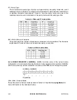
6.4.1.17 INPUT PORT REGISTER. The DUIP register shows the current state of the IPx
inputs.
DUIP
7
6
5
4
3
2
1
0
1
1
IP5
IP4
IP3
IP2
IP1
IP0
1
1
1
1
1
IP2
IP1
IP0
Read Only
IP5, IP4, IP3, IP2, IP1, IP0—Current State
1 = The current state of the respective IP input is logic one.
0 = The current state of the respective IP input is logic zero.
The information contained in these bits is latched and reflects the state of the input pins
at the time that the DUIP is read.
NOTE
These bits have the same function and value of the DUIPCR
bits 1 and 0.
IP5, IP4, and IP3 are not pinned out on the MC68306, and are
internally set to logic one.
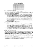
6.4.1.18 OUTPUT PORT CONTROL REGISTER (DUOPCR). The DUOPCR configures
six bits of the 8-bit parallel DUOP for general-purpose use or for auxiliary functions serving
the communication channels.

