MOTOROLA
MC68306 USER'S MANUAL
4- 3
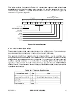
The status register, illustrated in Figure 4-2, contains the interrupt mask (eight levels
available) and the following condition codes: overflow (V), zero (Z), negative (N), carry (C),
and extend (X). Additional status bits indicate that the processor is in the trace (T) mode
and/or in the supervisor (S) state.
T
0
S
0
0
I2
I1
I0
X
N
Z
V
C
0
0
0
SYSTEM BYTE
USER BYTE
(CONDITION CODE REGISTER)
TRACE MODE
INTERRUPT
PRIORITY MASK
SUPERVISOR/USER STATE
EXTEND
NEGATIVE
ZERO
OVERFLOW
CARRY
15
14
13
12
11
10
9
8
7
5
6
4
3
2
1
0
EC2
Figure 4-2. Status Register
4.3.1 Data Format Summary
The processor supports the basic data formats of the M68000 family. The instruction set
supports operations on other data formats such as memory addresses.
The operand data formats supported by the integer unit (IU) are the standard twos-
complement data formats defined in the M68000 family architecture. Registers, memory,
or instructions themselves can contain IU operands. The operand size for each instruction
is either explicitly encoded in the instruction or implicitly defined by the instruction
operation. Table 4-1 lists the data formats for the processor. Refer to M68000PM/AD,
M68000 Family Programmer’s Reference Manual, for details on data format organization
in registers and memory.
Table 4-1. Processor Data Formats
Operand Data Format
Size
Notes
Bit
1 Bit
—
Binary-Coded Decimal (BCD)
8 Bits
Packed: 2 Digits/Byte; Unpacked: 1 Digit/Byte
Byte Integer
8 Bits
—
Word Integer
16 Bits
—
Long-Word Integer
32 Bits
—


