5- 4
MC68306 USER'S MANUAL
MOTOROLA
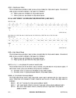
DUIPL2–0—DUART Interrupt Priority Level
This bit selects the interrupt priority level for the serial module.
000 = Reserved
001 = Interrupt priority level 1
010 = Interrupt priority level 2
011 = Interrupt priority level 3
100 = Interrupt priority level 4
101 = Interrupt priority level 5
110 = Interrupt priority level 6
111 = Interrupt priority level 7
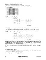
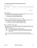
5.2.2 Timer Vector Register
FFFFFFFF
7
6
5
4
3
2
1
0
TVEC
7
TVEC
6
TVEC
5
TVEC
4
TVEC
3
TVEC
2
TVEC
1
TVEC
0
RESE
T:
0
0
0
0
1
1
1
1
SUPERVISOR ONLY
TVEC7–0—Timer Vector
The value set in this field supplies the vector for the DUART timer interrupt handler.
5.2.3 Bus Timeout Period Register
FFFFFFFC
7
6
5
4
3
2
1
0
BT7
BT6
BT5
BT4
BT3
BT2
BT1
BT0
RESE
T:
U
U
U
U
U
U
U
U
SUPERVISOR ONLY
A programmable-period timer can generate a bus error to terminate any bus cycle after 16
to 4096 wait states, programmable in 16-wait state increments. The bus timeout timer is
enabled by the BTEN bit in the system register.
The bus timeout timer restarts between the read and write portions of a TAS indivisible
cycle.
BT7–0—Bus Timeout Period
The value set in this field supplies the bus timeout timer period. The bus timeout timer
period can be calculated from the equation:
Period = (16
×
(register value +1))
×
EXTAL

