Accessories 2 - 23
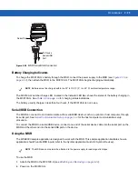
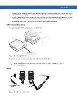
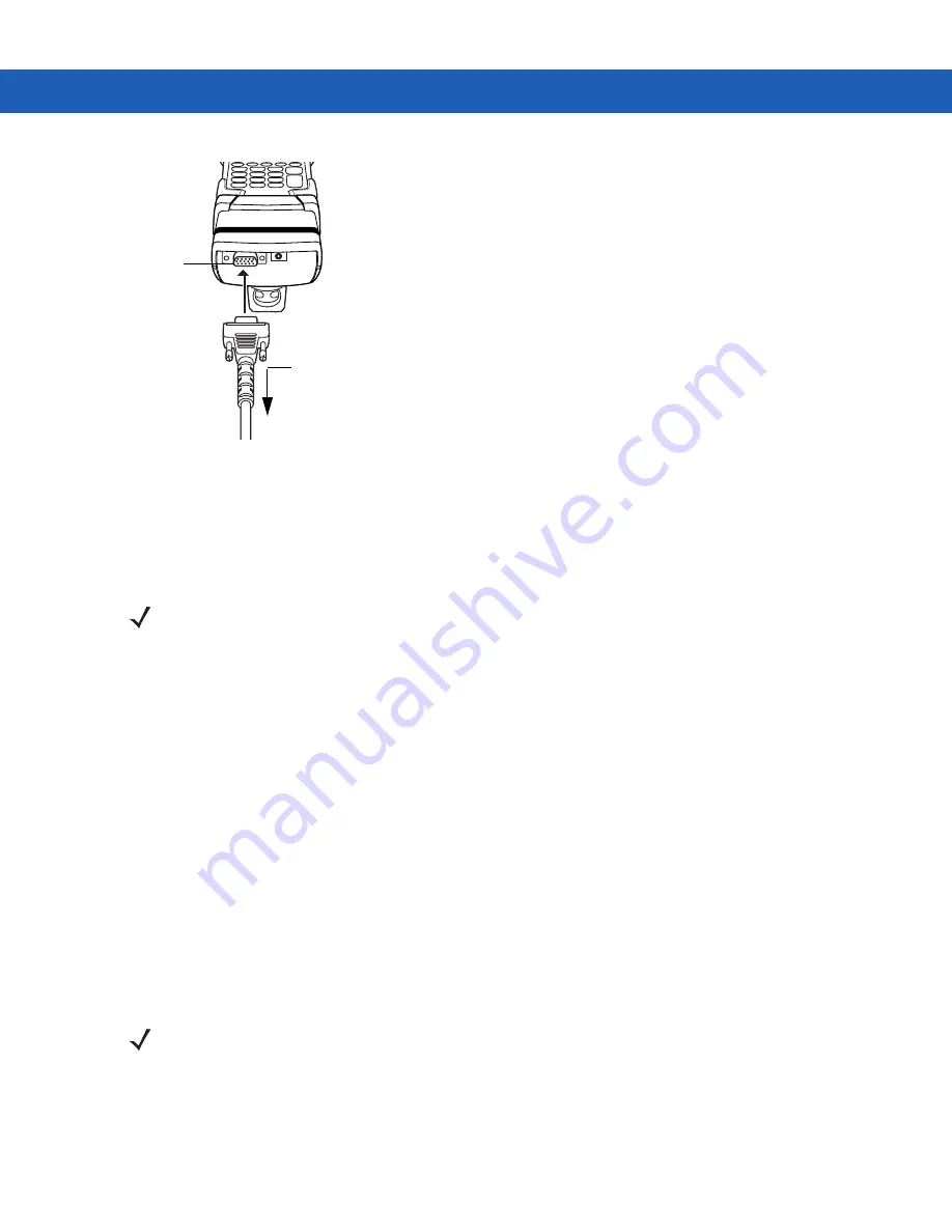
Figure 2-20
MSR Serial/USB Connection
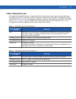
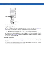
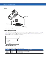
Battery Charging Indicators
To charge the MC9190-G’s battery through the MSR, connect the power supply to the MSR (see
), then attach the MSR to the MC9190-G. The MC9190-G begins charging automatically.
The MC9190-G’s amber charge LED, located in the Indicator LED Bar, shows the status of the battery charging in
the MC9190-G. See
for charging status indications.
The battery usually charges in less than four hours, if the MC9190-G is not in use.
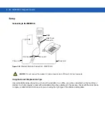
Serial/USB Connection
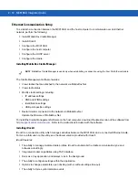
The MSR can connect to and communicate with a serial/USB device, such as a printer or host computer, through
its serial port. See
Serial Communication Setup on page 2-34
for the host computer communication setup
procedure.
To connect the MSR to a serial/USB device, connect one end of the serial device cable into the serial port on the
MSR and the other end into the serial/USB port on the device.
Using the MSR
The
MSR9000
sample
application is designed to work with the MSR. This sample application illustrates how an
application should handle MSR inputs (refer to the
Symbol Application Guide for Symbol Devices
).
To use the MSR:
1.
Attach the MSR to the MC9190-G (see
Attaching and Removing on page 2-22
2.
Power on the MC9190-G.
To Device
Serial/USB
Port
Serial Port
NOTE
Batteries must be charged within the 32° to 104° F (0° to +40° C) ambient temperature range.
NOTE
The MSR does not need to be attached to the power supply to read magnetic stripes.
Summary of Contents for MC9190-G
Page 1: ...MC9190 G Integrator Guide ...
Page 2: ......
Page 3: ...MC9190 G Integrator Guide 72E 140937 01 Rev A February 2011 ...
Page 6: ...iv MC9190 G Integrator Guide ...
Page 14: ...xii MC9190 G Integrator Guide ...
Page 66: ...2 42 MC9190 G Integrator Guide ...
Page 80: ...4 6 MC9190 G Integrator Guide ...
Page 114: ...7 6 MC9190 G Integrator Guide ...
Page 152: ...A 24 MC9190 G Integrator Guide ...
Page 176: ...C 6 MC9190 G Integrator Guide ...
Page 184: ...Glossary 8 MC9190 G Integrator Guide ...
Page 189: ......

