background image


Important Safety Measures  

1  

Reading Instructions


Read through all safety and operation 
instruction prior to operating the device. 


2  

Keeping Instructions


Keep all safety and operation instructions 
for future reference.


3  

Note & Warning Description


All warning descriptions on the device 
and in the operation instructions should 
be followed.


4  

Operate according to Instructions


All operation instructions should be 
followed.


5  

Cleaning


Unplug the device from its power supply 
prior to cleaning. Never use fluid 
detergent or aerosol. Instead, simply 
clean with a wet cloth.


6  

Accessories


Any accessory not recommended should 
not be used, and may result in danger.


7  

Water and Moisture


Do not use this device near a bathtub, 
basin, sink, washtub, swimming pool or 
other place near a water supply, nor in a 
damp basement; any of which may cause a 
“grounding” effect. 
 

8  

Supporting Equipment 


Don’t place the device on an unstable cart, 
block, tripod, bracket, or table. It may fall, 
resulting in serious personal injuries or 
damage to the device. 

9  

Ventilation


Openings and drilled holes in the cabinet are 
for ventilation to ensure its reliable operation 
and to prevent overheating. Do not place the 
device on a bed, sofa, carpet, or similar 
surface; otherwise, the openings may be 
blocked. Do not place the device near or on a 
radiator or hot air vent, nor inside a bookcase 
or shelf, unless proper ventilation is provided. 
Never stack other electronic equipment on the 
device. 

1 0  

Power Supply (110V) 


Only the power designated on the tab can be 
used (110V). If you are not sure what voltage 
your outlets support, please consult your local 
power supply company. 

1 1  

Protection of Power Cord


The power cord should not be walked upon 
nor overlaid by other cords or connectors. 


1 2  

Lightning Strike 

To properly protect the device in a 
lightning strike, or when unattended or 
not in use for a long time, please unplug 
from the power supply or disconnect the 
antenna or cable network. By doing so, 
the damage to the video product from 
lightning strikes or the over-loading of 
the power supply (surge) can be 
prevented. 

1 3  

Overloading 


Never overload the power supply circuit 
with other appliances, for it might lead 
to fire or electrical shock. 


Summary of Contents for MDV850T

Page 1: ...MDV850T User s Manual ...

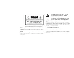
Page 2: ...COVER OR BACK NO USER SERVICEABLE PARTS INSIDE CAUTION Symbols and supplementary warning on the terminal button Note No extension cord socket or other lead wire should be used with the plug to avoid electrical shock The plug should be fully plugged in with no part exposed Never place the device where fluids may drop or splash Never place any object with fluids such as vases on the device Alert To ...

Page 3: ...s or damage to the device 9 Ventilation Openings and drilled holes in the cabinet are for ventilation to ensure its reliable operation and to prevent overheating Do not place the device on a bed sofa carpet or similar surface otherwise the openings may be blocked Do not place the device near or on a radiator or hot air vent nor inside a bookcase or shelf unless proper ventilation is provided Never...

Page 4: ...vice does not operate properly after following the directions for use described in this manual If this occurs adjust only the controls introduced in the instructions because any improper adjustment of other controls may result in damage and in most cases may require work by a qualified technician to have it work properly again e The device falls or the cabinet is damaged f Its performance undergoe...

Page 5: ...stallation If this equipment does cause harmful interference to radio or television reception which can be determined by turning the equipment off and on the user is encouraged to try to correct the interference by one or more of the following measures Reorient or relocate the receiving antenna Increase the separation between the equipment and receiver Connect the equipment into an outlet on a cir...

Page 6: ...anel 5 Remote Control 7 Main Service 11 Basic Front Panel Operations 12 Power On Off 12 Change Channel 12 Rear Panel Audio Video Connections 13 Record Connections 14 Rear Panel Connection Mono 15 Rear Panel Connection Stereo 16 Troubleshooting 18 ...

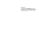
Page 7: ...everal solutions for integrating the box with your current entertainment audio and video system Please contact your service provider to ensure that the service is provided in your area Your service provider also provides instructions on optional services With other available applications and networks the MDV850T can provide hundreds of digital and analogue video channels If you encounter any diffi...

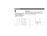
Page 8: ...UCTION Front Panel There are 7 keys and 2 indicators on the front panel of the MDV850T The keys perform basic functions Each control and their possible functions are described in the following figure and table ...

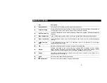
Page 9: ...or Indicator meaning there is a message 4 Remote Control Receiver Receives the remote control s signal 5 Menu Press to display the Settings menu 6 Ok Used to select or cancel while editing favorites also used to confirm a selection 7 Display Displays channel number error message 8 Four direction Moving Key Used to change channels and scroll through selections ...

Page 10: ...SERVICE PROVIDER TO ENSURE YOUR CONNECTION IS SUPPORTED BY THE SYSTEM Back Panel The MDV850T is designed to connect with several standard TV sets The back panel includes audio and video connectors and a Smart Card slot The connecting terminals and their possible functions are described in the following figure and table ...

Page 11: ...video connector to provide video for your TV set or video recorder 5 Left Sound Channel The single channel connector is used to provide the left channel audio signal to your stereo receiver 6 Right Sound Channel The single channel connector is used to provide the right channel audio signal to your stereo receiver 7 RS232 Port The RS232 Port is used by your service provider to offer quick solutions...

Page 12: ...ont panel of the unit as well When you use the menu except when in installation and reinstallation mode simply press the exit key whenever you wish to return the normal TV Radio mode The download of new software which can be executed in system update may change some functions of the unit The functions of the remote control are listed in the following table NOTE The remote control style may vary in...

Page 13: ...Channel Shifts to the nearest channel lower than the current channel 6 Main Menu Displays the main menu 7 Up Increase Channel Menu cursor moving and selection parameter adjustment Shifts up or down to the next program 8 Left Lower Volume Menu cursor moving and selection parameter adjustment In the video playing or audio state it can be used to lower the volume 9 Exit Exits the menu mode or returns...

Page 14: ...shifts between video audio and your favorites supporting function 19 Yellow Function Key In the video audio service mode it is connected twice in two seconds to check signal operation supporting function 20 Tab Returns to the upper layer of the menu to the last channel watched 21 Display Displays information on the current program including EPG information such as channel name program information ...

Page 15: ...selection parameter adjustment In the video playing or audio state it can be used to increase volume input 29 OK Confirms your selection reserved for play pause 30 Page up Turns to previous back page in the EPG menu 31 Volume Lowers volume in playing video or audio 32 Volume Increases volume in playing video or audio 33 Favorites Enters the favorites and shifts between favorite channels TV channel...

Page 16: ...Service to enter the main service menu which includes the following services these may vary depending upon your service provider select with up down keys and press OK to enter after entering press Program or Program to change to your desired channel ...

Page 17: ...is connected to the CABLE IN coaxial connection of your TV set the TV set must be adjusted to the output channel of the MDV850T The information is provided by your service provider Power On Off Press the On Off key on the front panel Change Channel Press the 4 direction moving key on the front panel of the MDV850T to select your desired channel ...

Page 18: ...nt system please read through the following For basic cable connection please use the equipped 75 ohm F connector coaxial cable The coaxial connection between the RF output terminal of the MDV850T and a standard TV set or video recorder cannot provide the stereo effect for the digital channel Please use the supplied cable of the single channel connector for the audio or video output Shut off the p...

Page 19: ...14 RECORD CONNECTIONS Please record the rear panel connections prior to using the MDV850T Prior to re connecting the system in the future please refer to this connection diagram for reference ...

Page 20: ...15 REAR PANEL CONNECTION MONO Mono Use this connection when you connect the MDV850T to your TV set or video player This method only provides monophonic sound ...

Page 21: ...6 REAR PANEL CONNECTION STEREO Stereo Follow this diagram when connecting a stereo TV or VCR Link the MDV850T to the video connector and left right sound channel connector of your TV set or video player ...

Page 22: ... to watch video using your TV set please ensure the video player is on No Video The cable signal may have not been transmitted to your house Check to ensure all cables are connected properly and the TV set is set to the cable TV channel designated by your service provider If necessary tighten the cable TV signal cable The signal cable of cable TV is not correct If you use base band video connectio...

Page 23: ...connection manually or reconnect the signal cable correctly Ensure the signal cable is not worn and the plug is not twisted or broken No Power The power cord is disconnected Reconnect the power cord Ensure the power socket in which the plug of the MDV850T is inserted always has a power supply The remote control does not work The battery is out of power Install fresh batteries in the remote control...

Page 24: ...20 521852 005 Rev B 08 07 English MGBI ...

Reviews: