Chapter 2: Infrastructure Device Installation
May 2008
2-10
Personality
Plug Type
Plug
Color
Part #
Function
Usage
If used
with
1.1
hardware
If used
with
2.0
hardware
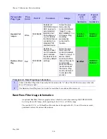
Standard PoE
Adapter
White
3863344B0
1
Enables all
MOTOMESH and
DUO devices to
send standard
IEEE 802.3af
PoE voltage
(48
Volts DC)
across
the PoE Ethernet
connection to a
standard PoE
enabled device.
Screw the plug
firmly onto the
connector labeled
“Select” on any
MOTOMESH 1.1 or
2.0 device. Plug
must stay
permanently
connected to
function.
Function
Enabled
Function
Enabled
Hardware Reset
Plug
Red
3863343B0
1
Performs a
hardware reset
on 2.0 hardware
which restores
the devices back
to factory default
settings.
Screw the plug
firmly onto the
connector labeled
“Select” on any 2.0
device. Wait 5
seconds and then
remove the plug to
automatically
perform a factory
reset and reboot
the device. Plug
must be removed
to complete this
process.
No effect
Function
Enabled
Procedure 2-3 Reset Plug Usage Information
BandPass Filter Usage Information
An optional BandPass filter (see graphic below) should be used when running a MOTOMESH DUO
device together with Canopy while operating in the 4.9, 5.4, or 5.8GHz range.
The specific 4.9, 5.4, or 5.8 BandPass filter attaches to the applicable 4.9, 5.4, and 5.8 antenna socket,
positioned between the unit and the antenna.
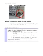
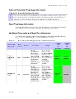
1
Connect the Reset Plug to the Personality Port located on the “A” side of the 4300 device, same side as the
Power ON indicator light.
2
The Hardware Reset Plug must be inserted for more than 4 seconds, and then removed.
Summary of Contents for MOTOMESH Duo 4300-49
Page 1: ...MOTOROLA MOTOMESH DUO 2 1 4300 Users Guide May 2008 ...
Page 2: ...MOTOMESH DUO 2 1 4300 Users Guide May 2008 ii This page intentionally left blank ...
Page 4: ...MOTOMESH DUO 2 1 4300 Users Guide May 2008 iv This page intentionally left blank ...
Page 8: ...May 2008 viii Blank page intentionally left blank ...
Page 12: ...List of Tables May 2008 xii This page intentionally left blank ...
Page 14: ...List of Procedures May 2008 xiv This page intentionally left blank ...
Page 22: ...Chapter 1 Product Introduction May 2008 1 8 This page intentionally left blank ...
Page 36: ...Chapter 2 Infrastructure Device Installation May 2008 2 14 This page intentionally left blank ...
Page 52: ...Chapter 3 Wiring Instructions May 2008 3 16 Figure 3 35 Finished Power Connector ...
Page 74: ...Chapter 6 Customer Service May 2008 6 4 This page intentionally left blank ...
Page 90: ...Glossary May 2008 Glossary 2 This page intentionally left blank ...

