background image

12

 October 12, 2006 

6809510A66-O

Product Overview

 MOTOSLVR L9/L72

there is no phonebook entry, the incoming phone number displays. If no caller 
identification information is available, an incoming call message displays.

Personal Information Management

The MotoSLVR L9/L72 telephones contain a built-in datebook with alarm 
reminders, message center, and a phonebook. 

Other Features

Detailed descriptions of other features available for the MotoSLVR L9/L72 
wireless telephones are in the appropriate User’s Guide listed in the Related 
Publications section toward the end of this manual.

User must subscribe to a caller line identification service through their service 
provider.

L9/L72 is the name used for this phone in the High Growth Markets (HGM), 
North Asia & Latin America regions. L9/L72 is the name used for this phone in 
the Europe region.

Summary of Contents for MOTOSLVR L72

Page 1: ...Level 1 and 2 Service Manual 6809510A66 O Wireless Telephone GSM 850 900 1800 1900 MHz GPRS EDGE MOTOSLVR tm L9 L72 ...

Page 2: ... service names are the property of their respective owners The Bluetooth trademarks are owned by their proprietor and used by Motorola Inc under license Motorola Inc 2007 All rights reserved Mobile Devices Business Sawgrass International Concourse 789 International Parkway Room S2C Sunrise FL 33325 6220 ...

Page 3: ... the Antenna Cap 21 Removing and Replacing the Transceiver PC Board Shield 22 Removing and Replacing the Transceiver PC Board 23 Removing and Replacing the Camera Assembly 26 Removing and Replacing the Front Housing 28 Removing and Replacing the Keypad 29 Removing and Replacing the Keypad PC Board 30 Removing and Replacing the Antenna 31 Removing and Replacing the Display Module 32 Subscriber Iden...

Page 4: ...4 October 12 2006 6809510A66 O Contents MOTOSLVR L9 L72 ...

Page 5: ...el number on the housing Use the entire model number when inquiring about the product Numbers are also assigned to chassis and kits Use these numbers when requesting information or ordering replacement parts Product Names Product names are listed on the front cover Product names are subject to change without notice Some product names as well as some frequency bands are available only in certain ma...

Page 6: ...h the Motorola product About this Service Manual Using this service manual and the suggestions contained in it assures proper installation operation and maintenance of wireless telephones Refer questions about this manual to the nearest Customer Service Manager Audience This manual aids service personnel in testing and repairing of wireless telephones Service personnel should be familiar with elec...

Page 7: ...rd Appointed Motorola Service Hubs will perform warranty and non warranty field service for level 2 assemblies and level 3 limited PCB component The Motorola High Technology Centers will perform level 4 full component repairs Customer Support Customer support is available through dedicated Call Centers and in country help desks Product Service training should be arranged through the local Motorola...

Page 8: ...793 7834 Replacement Parts Service Division RPSD Order replacement parts test equipment and manuals from RPSD U S A Outside U S A Phone 800 422 4210 Phone 847 538 8023 FAX 800 622 6210 FAX 847 576 3023 Website http businessonline motorola com EMEA Phone 49 461 803 1404 Website http emeaonline motorola com Asia Phone 65 648 62995 Website http asiaonline motorola com ...

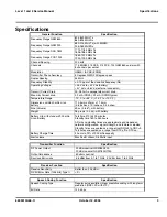
Page 9: ...with 840 mAh Li Ion battery 113 5mm x 49mm x 11 5mm 4 6 inches x 1 9 inches x 0 4 inches Size Volume 59 cc 3 6 in3 with battery Weight 96 grams 3 3 oz with battery Battery Life with standard 900 mAh Li Ion Battery Talk time 210 to 400 minutes Standby time 180 to 350 hours All talk and standby times are approximate and depend on network configuration signal strength and features selected Standby ti...

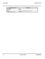
Page 10: ...2006 6809510A66 O Specifications MOTOSLVR L9 L72 Frame Duration 20 ms Block Length 260 bits Classes Class 1 bits 182 bits Class 2 bits 78 bits Bit Rate with FEC Encoding 22 8 kbps Speech Coding Function Specification ...

Page 11: ... telephones feature a 176 x 220 pixel display Features The MotoSLVR L9 L72 telephones use advanced self contained sealed custom integrated circuits to perform the complex functions required for GSM communication Aside from the space and weight advantage microcircuits enhance basic reliability simplify maintenance and provide a variety of operational functions Features available in the MotoSLVR L9 ...

Page 12: ...rm reminders message center and a phonebook Other Features Detailed descriptions of other features available for the MotoSLVR L9 L72 wireless telephones are in the appropriate User s Guide listed in the Related Publications section toward the end of this manual User must subscribe to a caller line identification service through their service provider L9 L72 is the name used for this phone in the H...

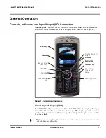
Page 13: ...62k TFT color display offering 7 lines of text 1 line of icons and 1 line of prompts The display provides constant graphical representations of battery capacity and signal strength as well as the real time clock 061507o Figure 1 Controls and Indicators Whether a phone displays all indicators depends on the programming and services to which the user subscribes Left Soft Key Open and Select menu ite...

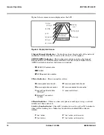
Page 14: ...5 Active Line Indicator Shows h to indicate an active call or g to indicate when call forwarding is on Indicators for dual line enabled SIM cards can include 050206o Figure 2 Display Idle Screen H GPRS PDP context active oe EDGE B GPRS packet data available L secure packet data transfer K unsecure packet data transfer N secure application connection M unsecure application connection S secure Circu...

Page 15: ...screen to indicate the battery charge level The gauge shows 4 levels 100 50 20 and low battery Battery Removal Removing the battery causes the phone to shut down immediately and loose any pending work For example partially entered phonebook entries or outgoing messages q IM active s invisible to IM r busy t offline É text message Ë voice message è voice text message é IM message õ loud ring Ì vibr...

Page 16: ...r to the appropriate User s Guide listed in the Related Publications section toward the end of this manual G If the battery is removed while receiving a message the message is lost To ensure proper memory retention turn the phone OFF before removing the battery Immediately replace the old battery with a fresh battery ...

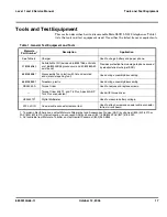
Page 17: ...7 Disassembly Tool plastic with flat and pointed ends manual opening tool Used during assembly disassembly 6680388B01 Tweezers plastic Used during assembly disassembly RSX4043 A Torque Driver Used to remove and replace screws Torque Driver Bits T3 and T6 Plus Apex 440 5IP Torx Plus or equivalent Used with torque driver HP34401A2 Digital Multimeter Used to measure battery voltage W FL LP IN Coaxial...

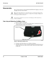
Page 18: ...replace align the battery cover with the rear housing 4 Place the battery cover on the rear housing and gently press the battery cover until it snaps into place Ensure that the battery door tap is tucked in below the RF cover G Many of the integrated devices used in this phone are vulnerable to damage from ESD Ensure adequate static protection is in place when handling shipping and servicing any i...

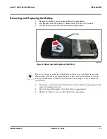
Page 19: ...he bottom of the battery into the battery compartment with contacts facing downward 5 Press the top of the battery into the battery compartment 6 Replace the battery cover as described in the procedures 061493o Figure 4 Removing and Replacing the Battery E There is a danger of explosion if the Lithium Ion battery is replaced incorrectly Replace only with the same type of battery or equivalent as r...

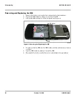
Page 20: ...older by sliding it away from the SIM 3 Lift up the SIM and remove it from the phone see Figure 5 4 To replace slide the SIM into the SIM holder with the notched corner located as shown 5 Lock the SIM holder by sliding it toward the SIM 6 Reassemble the battery and battery cover as described in the procedures 061495o Figure 5 Removing and Replacing the SIM SIM SIM Holder unlock ...

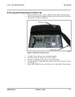
Page 21: ...release the antenna cover latches see Figure 9 3 Carefully lift the antenna cap away from the phone 4 To replace align the antenna cap over the antenna 5 Place the curved edge of the antenna cap onto the phone 6 Carefully press the straight edge of the antenna cap into place until the latches snap into place 7 Reassemble the SIM battery and battery cover as described in the procedures 061496o Figu...

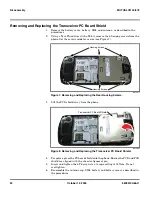
Page 22: ...t the PCB shield away from the phone 4 To replace place the PC board shield onto the phone Ensure the PCB and PCB shield are aligned with the chassis alignment pin 5 Insert and tighten the 6 T6 screws to a torque setting of 14 Ncm Do not overtighten 6 Reassemble the antenna cap SIM battery and battery cover as described in the procedures 061497o Figure 7 Removing and Replacing the Rear Housing Scr...

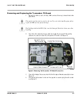
Page 23: ...e display flex connector with the flat edge of the disassembly tool see Figure 9 4 Use the metal tweezers to remove the speaker connector plug from its socket see Figure 9 G This product contains static sensitive devices Use anti static handling procedures to prevent ESD and component damage G The flexible printed cable FPC flex is easily damaged Exercise extreme care when handling 061499o Figure ...

Page 24: ...ure 12 to unseat the coaxial cable connector from the transceiver PC board see Figure 13 051259o Figure 10 Coaxial Cable Extraction Tool 051260o Figure 11 Coaxial Cable Extraction Tool Coaxial cable extraction tool Coaxial cable extraction tool Attach extraction tool opening to coax connector and pull upward ...

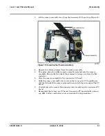
Page 25: ...cables and the coaxial cable 8 Lift the transceiver PC board completely out of the phone 9 To replace carefully insert the side edge of the transceiver PC board into the phone chassis Avoid damaging the battery pogo pins 10 Carefully re attach the display flex connector the main flex connector and the coaxial cable to the transceiver PC board Ensure the coaxial connector is positioned on the slot ...

Page 26: ...the disassembly tool to unseat the camera assembly flex connector from the transceiver PC board assembly see Figure 12 G This product contains static sensitive devices Use anti static handling procedures to prevent ESD and component damage G The flexible printed cable FPC flex is easily damaged Exercise extreme care when handling 061542o Figure 12 Removing the Camera Assembly Connector Camera asse...

Page 27: ... flex connector 6 Align the camera assembly to the transceiver PC board 7 Slide the camera assembly into its slot on the transceiver PC board Ensure that the flat side of the camera grommet lines up with the outer edge of the PC board 8 Carefully press the camera flex connector into its socket on the transceiver PC board 9 Reassemble the transceiver PC board transceiver PC board shield antenna cap...

Page 28: ...hone to release the housing catches along the sides of the front housing see Figure 14 4 Carefully lift and remove the front housing from the phone 5 To replace align the front housing to the phone 6 Lower the phone onto the front housing and keypad 7 Carefully and gently press the front housing into the chassis until all of the housing catches are engaged 8 Reassemble the transceiver PC board tra...

Page 29: ...ypad up from one corner as shown in Figure 15 and remove it from the front housing 3 To replace align the keypad holes with the front housing pins and place the keypad onto the front housing 4 Reassemble the front housing transceiver PC board transceiver PC board shield antenna cap SIM battery and battery cover as described in the procedures 061543o Figure 15 Removing and Replacing the Keypad Fron...

Page 30: ...re 16 3 Rotate the end of the PC board up and disconnect the flex connector underneath the keypad PC board see Figure 17 4 Use the coaxial cable extraction tool to disconnect the coaxial cable connector from the PC board and move the coaxial cable away from the PC board 5 Remove the silver colored chassis seal 061616o Figure 16 Removing the Keypad PC Board Screws 061544o Figure 17 Removing the Key...

Page 31: ...eiver PC board shield antenna cap SIM battery and battery cover as described in the procedures Removing and Replacing the Antenna 1 Remove the battery cover battery and SIM as described in the procedures 2 Use the plastic tweezers to lift the antenna assembly out of the phone see Figure 18 3 Carefully remove the antenna from the phone 4 To replace insert the antenna into the antenna slot on the ph...

Page 32: ...over the chassis assembly and use the metal tweezers to release the six display bracket latches located under the chassis assembly see Figure 19 3 Turn the chassis assembly over and lift the top edge of the display module see Figure 20 061619o Figure 19 Removing the Display Module Latches 061620o Figure 20 Removing the Display Module Display bracket latches Display bracket latches Display module P...

Page 33: ...assembly 6 Hold the side of the display module near the flex cable away from the chassis assembly 7 Carefully thread the display flex connector through the opening on the chassis assembly 8 Lower the display module fully onto the chassis assembly and gently press it into place 9 Reassemble the antenna keypad PC board keypad front housing transceiver PC board transceiver PC board shield antenna cap...

Page 34: ...ovide access to the net work Identification Each Motorola GSM phone is labeled with a variety of identifying numbers The following information describes the current identifying labels Mechanical Serial Number MSN The MSN is an individual unit identity number and remains with the unit throughout its life The MSN can be used to log and track a phone on Motorola s Service Center Database The MSN is d...

Page 35: ...etworks based on mobile station types or individual units The full IMEI structure is listed in Table 2 Where TAC Type Allocation Code formerly known as Type Approval Code NN Reporting body identifier XXXX Type Identifier ZZZZZZ Individual unit serial number A Phase 1 0 Phase 2 check digit defined as a function of all other IMEI digits Other label number configurations present are TRANSCEIVER NUMBE...

Page 36: ...one Identification Label MOTOROLA INC FCC ID IHDT5UV1 EE 3 CANADA 109 182 230A TYPE UVKA 832 2412 CHANNEL OPERATION SWF3001A H7 25821A2 VY SN D414AF0EYAA A56 G6 Mfg by Type approval information NAMPS info analog Transceiver model code 39 Transceiver model Board tracking ID G6VYY Radio SN ESN year month of mfg warranty code APC Code Radio serial no ESN yr month of mfg warr code Code 39 D414AF0E8AA ...

Page 37: ... SIM slot 5 Replace the battery as described in the procedures 6 Press u to turn the phone ON Manual Test Mode Commands Table 3 Manual Test Commands Key Sequence Test Function Name Remarks Menu 048263 Enter manual test mode End Key Exit manual test mode 54 Suspend Required for all Test Mode Operations 0 0 0 Select tone 0 0 0 1 Select tone 1 0 0 2 Select tone 2 0 0 3 Select tone 3 0 0 4 Select tone...

Page 38: ...d DCS 1800 10 0 5 10 0 6 Set dual band GSM 900 1800 10 1 0 Read band 3 GSM 4 DCS 5 PCS 6 GSM DCS 18 0 Initialize non volatile memory Master Reset 18 1 Initialize non volatile memory Master Clear 55 2 001 Test Display All pixels ON 55 2 000 Test Display All pixels OFF 55 2 002 Test Display Checkerboard pattern A 55 2 003 Test Display Checkerboard pattern B 55 2 004 Test Display Border pixels ON 06 ...

Page 39: ... board defective Replace the transceiver board refer to 1c Verify that the fault has been cleared and reassemble the phone with the new transceiver board 3 Display is erratic a Display module defective Temporarily replace the display module with a known good display module Verify that the fault is cleared and reassemble the phone with the new display module If the fault is still present proceed to...

Page 40: ...ective Replace vibrator If the fault has not been cleared proceed to b b Transceiver board defective Replace the transceiver board refer to 1c Verify that the fault has been cleared and reassemble the phone with the new transceiver board 8 Internal Charger not working Faulty charger circuit on transceiver board Test a selection of batteries in the rear pocket of the desktop charger Check LED displ...

Page 41: ... The following section provides a reference for the parts associated with MotoSLVR L9 L72 telephones Exploded View Diagram 061642o Figure 23 Exploded View Diagram 1 2 3 5 4 6 12 12 10 10 9 14 14 15 15 11 11 13 13 16 16 7 8 22 22 19 19 21 21 20 20 23 23 24 24 25 25 26 26 27 27 18 18 17 17 ...

Page 42: ... Assy Battery Latch 19 AAHN5861A Rear Hsg 7 3871077A02 Side Button VOL 20 0170386F06 Assy Flex Interconnection 8 3871079A02 Side Button Smart 21 0170298Z26 Antenna Assy 9 3871099A02 Side Button Camera 22 0170298Z13 Polyphonic Speaker Assy 10 0170392C01 Assy Chassis 23 0571084A01 T Flash Cover 11 5989889N01 Vibrator 24 0170386F20 Assy Keypad PCB 12 AALG4365AA Assy Main PCB 25 0371383A01 T5 Screws 1...

Page 43: ... European Kit OnTourMBBLKE JBL On Tour Mobile portable speaker US Kit OnTourMBBLK JBL On Tour Mobile speaker PRC kit CH1414A JBL On Tour Mobile speaker UK kit OnTourMBBLKU S805 DJ Headset Bluetooth Music and Telephony SYN1673 JBL Black On Tour Portable Speaker SYN1451 H500 Bluetooth Headset Fire Red SYN1667 H500 Bluetooth Headset Celery SYN1732 H500 Bluetooth Headset Pumpkin SYN1733 H500 Bluetooth...

Page 44: ...omotive Bluetooth Car Kit HF850 98675H Bluetooth Car Kit IHF1000 Americas Asia 98676J Bluetooth Car Kit IHF1000 EMEA CFLN1232AB Bluetooth Car Kit High Tier T505 SYN1717 Bluetooth Car Kit Mid Tier T305 SYN1716 Data and Enterprise 1GB micro SD card Mot SD adapter SYN1406 128MB micro SD card Mot SD adapter SYN1403 256MB micro SD card Mot SD adapter SYN1404 32MB micro SD card Mot SD adapter SYN1401 51...

Page 45: ...itcher UK HK SPN5190 Travel Charger EMU Mid Rate Switcher US ENG SPN5185 Travel Charger EMU Rapid Switcher Argentina SPN5197 Travel Charger EMU Rapid Switcher BRAZIL SPN5196 Travel Charger EMU Rapid Switcher HK SPN5199 Travel Charger EMU Rapid Switcher MEXICO SPN5200 Travel Charger EMU Rapid Switcher PRC SPN5198 Travel Charger EMU Rapid Switcher US SPN5202 Travel Charger EMU Rapid TWN SPN5270 Vehi...

Page 46: ...s MOTOSLVR L9 L72 Related Publications Programming Software Upgrade and Flexing Contact your local technical support engineer for information about equipment and procedures for flashing and flexing MotoSLVR L9 L72 User s Guide English 68XXXXX163 ...

Page 47: ...equipment identity 35 mechanical serial number 34 product 5 identification labels 34 36 IMEI 35 Introduction 5 K keypad PC board removing and replacing 29 30 keypad removing and replacing 29 L LCD 13 liquid crystal display LCD 13 M manual test mode 37 MSN 34 N names product 5 O operation 13 battery 15 controls indicators and I O connectors 13 icons 14 LCD 13 overview product 11 P parts exploded vi...

Page 48: ...34 service manual about 6 audience 6 conventions 7 scope 6 service policy 7 customer support 7 out of box failure 7 product support 7 shut down upon battery removal 15 SIM description 34 SIM removing and replacing 20 specifications 9 subscriber identity module SIM 34 support customer 7 product 7 T test equipment 17 tools disassembly 17 Transceiver PC Board Shield removing and replacing 22 Transcei...

Page 49: ......
Reviews: