


44
October 12, 2006
6809510A66-O
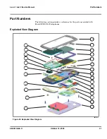
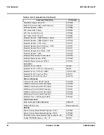
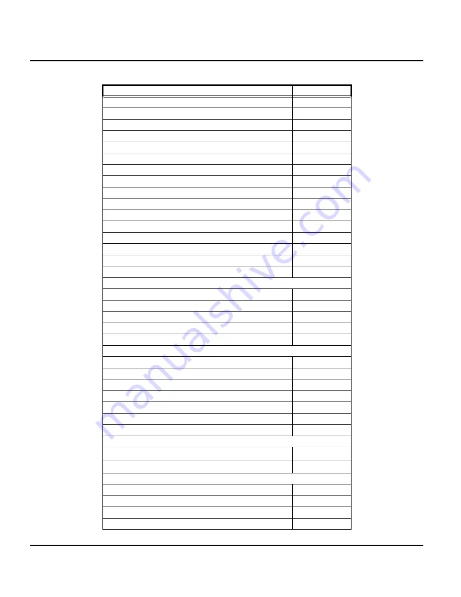
Part Numbers
MOTOSLVR L9/L72
Blue/Black Cingular Only H700
SYN1508
Black H700 (not available in North America)
SYN1509
Bluetooth Headset - HS805
SYN0986
H670 Black Slate (Canary)
SYN1853
H670 Cosmic Blue (Canary)
SYN1855
H670 Silver Quartz (Canary)
SYN1852
Bluetooth Headset - HS850 (Refresh - Black)
SYN1107
Bluetooth Headset - HS850 (Refresh - Blue)
SYN1226
Bluetooth Headset - H700 (silver)
SYN1311
Bluetooth Headset (Pearl Dark Gray) - H300
SYN1297
Bluetooth Headset (Pink) - H300
SYN1417
Bluetooth Headset (Pure White) - H300
SYN1416
Bluetooth Headset - H605
SYN1303
Bluetooth Mono Headset, Nickel- H500
SYN1290
Bluetooth Stereo Headset HT820
SYN0948
Bluetooth Stereo Transceiver DC800
SYN1001
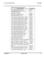
Automotive
Bluetooth Car Kit - HF850
98675H
Bluetooth Car Kit - IHF1000 - Americas/Asia
98676J
Bluetooth Car Kit - IHF1000 - EMEA
CFLN1232AB
Bluetooth Car Kit - High Tier, T505
SYN1717
Bluetooth Car Kit - Mid Tier, T305
SYN1716
Data and Enterprise
1GB micro SD card & Mot SD adapter
SYN1406
128MB micro SD card & Mot SD adapter
SYN1403
256MB micro SD card & Mot SD adapter
SYN1404
32MB micro SD card & Mot SD adapter
SYN1401
512MB micro SD card & Mot SD adapter
SYN1405
64MB micro SD card & Mot SD adapter
SYN1402
Bluetooth Class 1 USB Adapter PC850
SYN1244
Digital Accessories
Data Cable Mini USB/USB/Serial
SKN6371
Mobile Phone Tools
Region-specific
Modules
Reverb (Oakley Stereo Bluetooth Eyewear - BLK)
SYN1552
Reverb (Oakley Stereo Bluetooth Eyewear - WHT)
SYN1553
REVERB (Oakley Stereo Bluetooth Eyewear Brown. Sm.)
SYN1554
Oakley RAZRWIRE (Mercury: NA) - H7
98679H
Table 6. List of Accessories (Continued)
Accessory Description
Kit Number
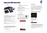
Summary of Contents for MOTOSLVR L72
Page 4: ...4 October 12 2006 6809510A66 O Contents MOTOSLVR L9 L72 ...
Page 49: ......