background image

68000222001-B

November 10, 2008 

INDEX-1

Level 1 and 2 Service Manual


INDEX

INDEX

A

active line indicator 14
airplane mode 13
alert settings 14
alert style profiles 14

B

battery

function 14
gauge 14
removing 18

battery housing

removing 18

battery indicator 14
Bluetooth indicator 14

C

call forward indicator 14
Canadian Interference-Causing Equipment regulations 3
changes

product 3

conventions 5
copyrights

computer software 4

D

disassembly 18

E

EDGE indicator 13
exploded view parts list 53

F

FCC rules 3
features

SIM Toolkit 10
voice recognition 10

G

GPRS indicator 13

I

identification 50

international mobile station equipment identity 51
mechanical serial number 50

product 3

IM indicators 14
IMEI 51
in-call indicator 14
Introduction 3

L

Low Battery message 14

M

menu

structure diagram 14

message indicator 14
MSN 50

N

names

product 3

O

operation

controls, indicators, and I/O 11

operation, general 11
overview, product 9

P

parts

exploded view parts list 53

product

changes 3
identification 3
names 3

product overview

features 9

profile indicator 14
profiles 14

R

regulatory agency compliance 3
removing

battery 15, 18
battery housing 18
SIM 21
speaker cover 22

replacement parts

contact information 5

replacing

battery 18

1 and 2

68000222001-B
 ZN5

Summary of Contents for MOTOZINE ZN5

Page 1: ...Level 1 2 Service Manual 68000222001 B GSM 850 900 1800 1900 MHz GPRS EDGE MOTOZINE ZN5 ...

Page 2: ...in the US Patent Trademark Office All other product or service names are the property of their respective owners Motorola Inc 20008 All rights reserved Mobile Devices Business Mail Drop 42 16A 8000 West Sunrise Boulevard Plantation Florida 33322 9947 ...

Page 3: ...ntity Module SIM 23 Removing and Replacing the Speaker Cover 24 Removing and Replacing the Rear Housing and Its Components 27 Removing and Replacing Front Housing 32 Removing and Replacing Display 33 Assembly 37 Installing the Display 41 Installing the Daughter Board 41 Installing the Display Module 42 Installing the PCB into the Front Housing 43 Installing the Camera Module Assembly 45 Installing...

Page 4: ...2 November 10 2008 68000222001 B Contents ZN5 ...

Page 5: ...ment parts Product Names Product names are listed on the front cover Product names are subject to change without notice Some product names as well as some frequency bands are available only in certain markets Product Changes When electrical mechanical or production changes are incorporated into Motorola products a revision letter is assigned to the chassis or kit affected for example A B or C and ...

Page 6: ... computer programs with the Motorola product About this Service Manual Using this service manual and the suggestions contained in it assures proper installation operation and maintenance Refer questions about this manual to the nearest Customer Service Manager Table 1 shows the revision history of this service manual Audience This manual aids service personnel in testing and repairing ZN5 telephon...

Page 7: ...not refurbished as standard Appointed Motorola Service Hubs will perform warranty and non warranty field service for level 2 assemblies and level 3 limited PCB component Motorola High Tech Centers will perform level 4 full component repairs Customer Support Customer support is available through dedicated Call Centers and in country help desks Product Service training is available through the local...

Page 8: ...ment parts test equipment and manuals from RPSD U S A Outside U S A Phone 800 422 4210 Phone 847 538 8023 FAX 800 622 6210 FAX 847 576 3023 Website http businessonline motorola com EMEA Phone 49 461 803 1346 Website http emeaonline motorola com Asia Phone 65 648 62995 Website http asiaonline motorola com ...

Page 9: ...pical Temperature Range 10 C to 55 C 15 F to 130 F Dimensions with 970 mAh Li Ion battery 50 5mm x 117 95mm x 11 8mm 14 9 Bump at the battery door Size Volume TBD cc Weight TBD grams with battery Battery Life with standard 970 mAh Li Ion Battery Standard Talk Time up to 342min Standard Standby Time up to 571 hours WLAN Talk Time up to 160min WLAN Standby Time up to 97 hours All talk and standby ti...

Page 10: ... Specification Speech Coding Type Regular pulse excitation linear predictive coding with long term prediction RPE LPC with LTP Bit Rate 13 0 kbps Frame Duration 20 ms Block Length 260 bits Classes Class 1 bits 182 bits Class 2 bits 78 bits Bit Rate with FEC Encoding 22 8 kbps ...

Page 11: ... AMLCD with white pixels on a black background The camera module is a 5 0 mega pixel VGA CMOS camera with flash The main circuit board contains the Receiver Transmitter Synthesizer and Control Logic Circuitry and phone electronics The telephones are made of polycarbonate plastic The display and speaker as well as the 23 key keypad transceiver printed circuit board PCB microphone charger and headph...

Page 12: ...olkit is a value added service delivery mechanism that allows GSM operators to customize the services they offer their customers from the occasional user who requests sports news and traffic alerts to a high call time business user who receives stock alerts and checks flight times Operators can now create their own value added services menu quickly and easily in the phone The customized menu will ...

Page 13: ...ad See Figure 1 070062o Figure 1 Controls Indicators and I O Make answer calls Volume Zoom Keys Left Soft Key Lanyard Hook Micro USB Port Scroll up down left right Turn on off hang up exit menus Right Soft Key Back Clear Key Lock Unlock Keypad 3 5mm Headset Jack Battery Charge Indicator Light Bluetooth Headset Indicator Light Open menu select menu items Camera Key Review Key Delete Key Preview Tog...

Page 14: ...ens the initial menu structure or allows access to a submenu Soft keys refer to non labeled keys that correspond to text options displayed on the screen The left and right soft keys perform the function shown in the corners of the display The right key will usually select an option whereas the left key will usually exit a function or return to a previous screen see Figure 3 070063o Figure 2 Additi...

Page 15: ...one is using a high speed Enhanced Data for GSM Evolution EDGE or General Packet Radio Service GPRS network connection Indicators can include 070048o 070049o Figure 3 Icon Indicators Whether a phone displays all indicators depends on the programming and services to which the user subscribes EDGE connection GPRS connection 5 EDGE data transfer GPRS data transfer 4 EDGEsecure data transfer 8 GPRS se...

Page 16: ... to indicate when call forwarding is on Indicators for dual line enabled SIM cards can include 9 Battery Level Indicator Vertical bars show the battery charge level Battery Function Battery Gauge The telephone displays a battery level indicator icon in the idle screen to indicate the battery charge level The gauge shows four levels 100 66 33 and Low Battery solid blue Bluetooth powered on solid gr...

Page 17: ...shut down and any pending work for example partially entered phone book entries or outgoing messages is lost Operation For detailed operating instructions refer to the appropriate User s Guide To ensure proper memory retention turn OFF the phone before removing the battery G If the battery is removed while receiving a message the message will be lost ...

Page 18: ...16 November 10 2008 68000222001 B General Operation ZN5 ...

Page 19: ...arger Used to charge battery and to power device 0180386A82 Antistatic Mat Kit includes 66 80387A95 antistatic mat 66 80334B36 ground cord and 42 80385A59 wrist band Provides protection from damage to device caused by electrostatic discharge ESD 6680388B67 Disassembly tool plastic with flat and pointed ends manual opening tool Used during assembly disassembly of device 6680388B01 Tweezers plastic ...

Page 20: ...SD Ensure adequate static protection is in place when handling shipping and servicing the internal components of this equipment G Use extreme caution when handling this device to avoid scratching or blemishing the external finishes of the phone E All batteries can cause property damage and or bodily injury such as burns if a conductive material such as jewelry keys or beaded chains touch exposed t...

Page 21: ...ce Manual Disassembly 3 Lift up and remove the battery cover 4 Lift the battery door away from the phone 5 Grasp the battery along the edges and lift up v538882 Figure 2 Removing the Battery Door v538884 Figure 3 Removing the Battery Battery cover Battery ...

Page 22: ...ry compartment 8 Lower the opposite edge of the battery into the battery compartment 9 Align and lower the battery cover onto the phone then push the cover down and snap it into place E There is a danger of explosion if the Lithium Ion battery is replaced incorrectly Replace only with the same type of battery or equivalent as recommended by the battery manufacturer Dispose of used batteries accord...

Page 23: ...ttery door and battery as described in the procedures 2 Slide the SIM out of the SIM holder 3 Carefully lift the SIM from the phone 4 To replace insert the SIM into the holder ensuring the cut corner of the SIM faces the top edge of the phone 5 Replace the battery and battery door as described in the procedures v525075 Figure 4 Removing the SIM SIM ...

Page 24: ... door and battery as described in the procedures 2 Insert the black stick tool with the flat end into the opening between the speaker cover and the front housing 3 Move the black stick along the housing edge to disengage the 3 snaps v525076 Figure 5 Removing the Speaker Cover Part One Speaker Cover ...

Page 25: ... Snaps must be pushed out against battery compartment to disengage 5 Press the speaker cover against the south end Open to disengage the snaps at the bottom v538887 Figure 6 Removing the Speaker Cover Part Two v538888 Figure 7 Removing the Speaker Cover Part Three Speaker Cover ...

Page 26: ...g 7 Discard the speaker cover Do not reuse the speaker cover for assembly Removing the USB Grommet 1 Pull the USB grommet out from housing and then lift it up to remove 2 Remove the USB Grommet v538889 Figure 8 Discard the Speaker Cover v538889 Figure 9 Removing the USB Grommet USB Grommet ...

Page 27: ...e Rear Housing and Its Components 1 Using a Torx driver with a T 5 bit remove the six housing screws Retain the screws for reassembly 2 Insert black stick and release the rear housing snaps v538890 Figure 10 Removing the Housing Screws v538891 Figure 11 Removing the Housing Rear Housing ...

Page 28: ... Lift the rear housing from the phone 4 Remove the rear housing from the phone 5 Remove the headset jack connector from the rear housing v538892 Figure 12 Removing the Housing v538893 Figure 13 Removing the Headset Jack Connector Headset Jack Connector ...

Page 29: ...d 2 Service Manual Disassembly Removing the Speaker Housing 1 Pull up the Speaker Housing from the battery area until the speaker housing snaps disengage 2 Remove the speaker housing v538893 Figure 14 Removing the Speaker Housing Speaker Housing ...

Page 30: ... of a black stick under the side key flex connector and lift up to disengage it 2 Insert the flat edge of a black stick under the camera flex connector and lift up to disengage it v538895 Figure 15 Removing the Side Key Flex Connector v538896 Figure 16 Removing the Flash Flex Connector Connector Flash Flex Connector ...

Page 31: ...sert the flat part of a black stick under the camera flex connector and lift up to disengage it 4 Lift the flash and camera modules out of the phone v538897 Figure 17 Removing the Flash Flex Connector v538898 Figure 18 Removing the Camera Module Camera Flex Connector Camera Module ...

Page 32: ...o the right side Do not stretch the keypad flex 2 Insert the flat edge of a black stick under the keypad connector as shown in picture and lift up to disengage it v538899 Figure 19 Preparing to Remove the Front Housing v538900 Figure 20 Removing the Keypad Flex Connector PCB Keypad Flex Connector ...

Page 33: ...Service Manual Disassembly 3 Remove the front housing Removing the Display 1 Rotate the display until the hooks disengage Do not touch the display glass 2 Place the display beside the PCB Do not stretch the flex v538901 Figure 21 Removing the Display ...

Page 34: ...ack stick disconnect the daughter board connector by rotating the black stick as shown Be aware of the spring contacts on main board v538903 Figure 22 Removing the Daughter Board Connector v538904 Figure 23 Removing the Daughter Board Daughter Board Daughter Board ...

Page 35: ...sembly 4 Use a black stick to open the ZIF door Avoid damage to the door Heating the daughter board with a heating gun at a temperature of 90 degrees allows the daughter board to be easily disconnected v538905 Figure 24 Opening the Daughter Board Connector ZIF Connector ...

Page 36: ...34 November 10 2008 68000222001 B Disassembly ZN5 5 Remove the display flex from the ZIF connector 6 Remove the display module v538906 Figure 25 Removing the Display Module Flex Connector Display Flex ...

Page 37: ...mber 10 2008 35 Level 1 and 2 Service Manual Assembly Assembly Installing Speaker Poron Pad and Mic Boot 1 Place the Speaker Poron pad in the marked area on the main PCB v541674 Figure 26 Installing the Speaker Poron Pad ...

Page 38: ...36 November 10 2008 68000222001 B Assembly ZN5 2 Press fit the Microphone Boot onto the Microphone v541675 Figure 27 Installing the Microphone Boot ...

Page 39: ...Assembly Installing Poron Pad and labels 1 Place a Poron pad on the marked area of the Daughter Board 2 Place double sided adhesive tape on the marked area See Figure 28 v538906 Figure 28 Placing the Poron Pad and Double Sided Adhesive Daughter Board Adhesive Poron ...

Page 40: ...38 November 10 2008 68000222001 B Assembly ZN5 3 Place a water detection label on the marked area Correct placement is important v538907 Figure 29 Placing the Water Detect Label Water Detect Label ...

Page 41: ...hite line to ensure the display flex is correctly inserted Installing the Daughter Board 1 Remove the liner from double sided adhesive tape on the daughter board 2 Place the Daughter PCB onto the Main PCB Make contact with the Board To Board BTB connector first and then make contact to adhesive tape Use wall as a guide v538907 Figure 30 Inserting the Display Flex into ZIF Connector ...

Page 42: ...r Installing the Display Module 1 Place the display module on the PCB and turn the display until is locked in position 2 Ensure hooks are around PCB edge and dimples are in guide holes v538910 Figure 31 Connecting the BTB Connectors v541660 Figure 32 Inserting the Display onto the Main PCB ...

Page 43: ...emove the liner from the Mic Mesh in the front housing 2 Place and Press the Keyboard connector firmly into the PCB BTB connector 3 Remove the liner from the display and also from the inside of the front housing Do not touch glass with after removing the liners 4 Clean the front housing lens and display with ionized air v541661 Figure 33 Attaching Flex Connectors to Main PCB ...

Page 44: ...to the front housing using the screw bosses as a guide 6 Earpiece speaker springs must be under the PCB v541662 Figure 34 Installing the Main PCB into the Front Housing Be aware of the correct placement of the PCB in top of housing v541662 Figure 35 Installing the Main PCB into the Front Housing ...

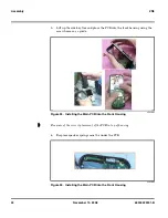
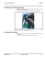
Page 45: ...CB The camera must be angled under the daughter board 2 Connect the camera module flex connector BTB to the daughter board Installing the Flash Module 1 Place the flash module into the opening on the main PCB sliding it from the south direction 2 Connect the flash module flex connector to the daughter board v541664 Figure 36 Installing the Camera Module to Main PCB ...

Page 46: ...ash module Connecting the Side Key Flex Assembly 1 Connect the Side key Flex to the daughter board Use corner of the shield to align the connector v541665 Figure 37 Installing the Flash Module to the Main PCB v541666 Figure 38 Connecting the Side Key Flex to Main PCB Align Here ...

Page 47: ...the speaker box assembly into the front housing using the bottom of housing as a guide 3 Press on the speaker box until locked to front housing Installing the Rear Housing Assembly 1 Remove half part of board label and place in the rear housing as shown v541667 Figure 39 Installing the Speaker Housing Assembly v541668 Figure 40 Installing the Rear Housing Assembly ...

Page 48: ...g 3 Remove the liner from the Camera module 4 Slowly angle the rear side onto front with the north side first Be aware there is guiding from the camera module flash module and headset jack 5 Press on side of Rear side to engage the hooks to the front housing v541669 Figure 41 Installing the Rear Housing Assembly ...

Page 49: ...module trough hole in the rear housing is level 7 Insert and drive the six housing screws Start with screws at the top then middle screws and then the screws at bottom torque setting 16 Ncm v541670 Figure 42 Installing the Rear Housing Assembly v538890 Figure 43 Installing the Rear Housing Screws ...

Page 50: ...opening within the housing 2 Press the USB Grommet firmly into place to engage the retention feature to the housing Installing the Speaker Cover 1 Attach a new speaker cover near the battery chamber Ensure all 3 hooks are engaged v541671 Figure 44 Installing the USB Grommet Note Do not reuse old speaker cover for assembly ...

Page 51: ...2008 49 Level 1 and 2 Service Manual Assembly 2 Place the speaker cover over the guiding holes at the bottom and press until locked in place 3 Install SIM battery and battery cover v541672 Figure 45 Installing the Speaker Cover ...

Page 52: ...is replaced Personality transfers reproduce the customer s original personalized details such as menu and stored memory such as phone books or even just program a unit with basic user information such as language selection ZN5 telephones use Motorola Phone Tools synchronization software to effect a personality transfer Identification Each Motorola GSM device is labeled with a variety of identifyin...

Page 53: ...orks based on mobile station types or individual units The full IMEI structure is listed in Table 2 Where TAC Type Allocation Code formerly known as Type Approval Code NN Reporting body identifier XXXXXX Type Identifier ZZZZZZ Individual unit serial number A Phase 1 0 Phase 2 check digit defined as a function of all other IMEI digits Other label number configurations present are TRANSCEIVER NUMBER...

Page 54: ...52 November 10 2008 68000222001 B Part Numbers ZN5 Part Numbers v541673 Figure 47 Exploded View Diagram ...

Page 55: ...103619F05 FRONT HOUSING ASSY ARABIC 2 0503580S01 GROMMET USB 3 7271375G01 DISPLAY ASSY 4 CFLG1090AA PCBA MAIN 4 CHLG4635AA PCBA MAIN 4 SLG5584AA PCBA MAIN 5 3203571B97 GASKET ACOUSTIC 6 1103592S03 ADHESIVE DAUGHTER BOARD 7 7589902Z08 PORON PAD 7 0x7 0mm 8 7589902Z01 PORON PAD 8 00x3 00mm 9 CFLG1089AA DAUGHTER BOARD 10 01004021001 CAMERA 11 0103618F01 FLASH LIGHT ASSY 12 0971177D01 CONNECTOR HSJ 3 ...

Page 56: ...54 November 10 2008 68000222001 B Part Numbers ZN5 ...

Page 57: ...it 10 voice recognition 10 G GPRS indicator 13 I identification 50 international mobile station equipment identity 51 mechanical serial number 50 product 3 IM indicators 14 IMEI 51 in call indicator 14 Introduction 3 L Low Battery message 14 M menu structure diagram 14 message indicator 14 MSN 50 N names product 3 O operation controls indicators and I O 11 operation general 11 overview product 9 P...

Page 58: ...oduct support 5 service procedure ordering replacement parts 5 shut down upon battery removal 15 signal strength indicator 13 SIM Application Toolkit 10 SIM card 50 personality transfer 50 SIM removing and replacing 21 speaker cover removing and replacing 22 specifications 7 support customer 5 product 5 T tools and test equipment 17 U user interface diagrams 14 V voice recognition 10 W warranty se...

Page 59: ......

Page 60: ......

Reviews: