6-8
MPC8240 Integrated Processor User’s Manual
SDRAM Interface Operation
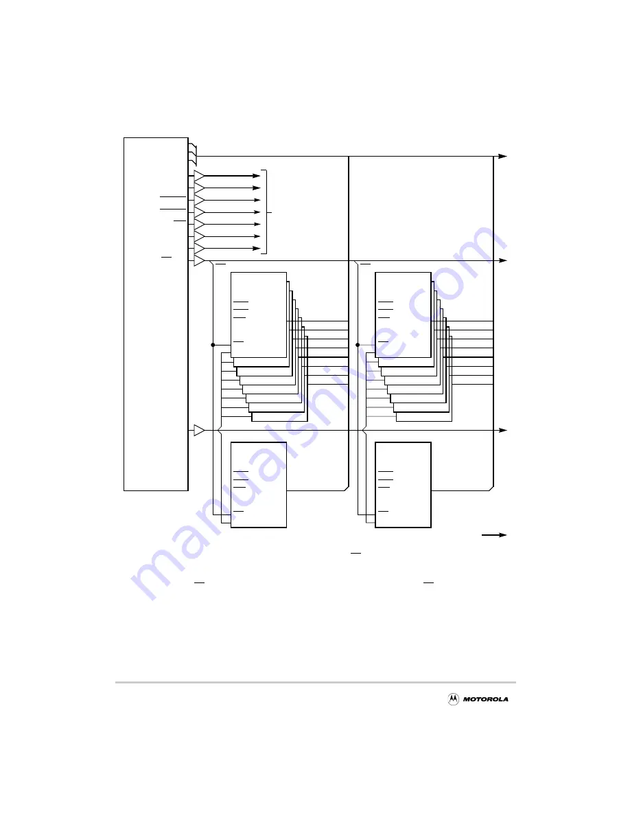
Figure 6-3. Example 512-MByte SDRAM Configuration With Parity
CAS
CS
RAS
WE
CKE
CLK
DQM
A[0-11]
2Mx8 SDRAM
DQ[0-7]
BA[0-1]
CAS
CS
RAS
WE
CKE
CLK
DQM
A[0-11]
2Mx8 SDRAM
DQ[0-7]
BA[0-1]
CAS
CS
RAS
WE
CKE
CLK
DQM
A[0-11]
2Mx8 SDRAM
DQ[0-7]
BA[0-1]
CAS
CS
RAS
WE
CKE
CLK
DQM
A[0-11]
2Mx8 SDRAM
DQ[0-7]
BA[0-1]
CAS
CS
RAS
WE
CKE
CLK
DQM
A(11-0)
2Mx8 SDRAM
DQ(7-0)
BA(1-0)
CAS
CS
RAS
WE
CKE
CLK
DQM
A(11-0)
2Mx8 SDRAM
DQ(7-0)
BA(1-0)
CAS
CS
RAS
WE
CKE
CLK
DQM
A[0-11]
2Mx8 SDRAM
DQ[0-7]
BA[0-1]
CAS
CS
RAS
WE
CKE
CLK
DQM
A[11:0]
8Mx8 SDRAM
DQ[7:0]
BA[1:0]
0
MDH[0:7]
MDH[8:15]
MDH[16:23]
MDH[24:31]
MDL[0:7]
MDL[8:15]
MDL[16:23]
MDL[24:31]
1
2
3
4
5
6
7
0
MDH[0:7]
1
2
3
4
5
6
7
CAS
CS
RAS
WE
CKE
CLK
DQM
A[11:0]
8Mx8 SDRAM
DQ[7:0]
BA[1:0]
0
PAR[0:7]
SDRAS
SDCAS
WE
CKE
SDRAM_CLK[0:3]
CS[0:7]
SDBA[1:0]
SDMA[12:0]
MDH[0:31]
MDL[0:31]
PAR[0:7]
MPC8240
DQM[0:7]
CS0
CAS
CS
RAS
WE
CKE
CLK
DQM
A[11:0]
8Mx8 SDRAM
DQ[7:0]
BA[1:0]
1
PAR[0:7]
CS1
Bank 1
8M x 72
64 MByte
To all SDRAM
Devices in
Common
Memory Data Bus
Bank 0
8M x 72
64 MByte
DQM0
DQM1
CAS
CS
RAS
WE
CKE
CLK
DQM
A[0-11]
2Mx8 SDRAM
DQ[0-7]
BA[0-1]
CAS
CS
RAS
WE
CKE
CLK
DQM
A[0-11]
2Mx8 SDRAM
DQ[0-7]
BA[0-1]
CAS
CS
RAS
WE
CKE
CLK
DQM
A[0-11]
2Mx8 SDRAM
DQ[0-7]
BA[0-1]
CAS
CS
RAS
WE
CKE
CLK
DQM
A[0-11]
2Mx8 SDRAM
DQ[0-7]
BA[0-1]
CAS
CS
RAS
WE
CKE
CLK
DQM
A(11-0)
2Mx8 SDRAM
DQ(7-0)
BA(1-0)
CAS
CS
RAS
WE
CKE
CLK
DQM
A(11-0)
2Mx8 SDRAM
DQ(7-0)
BA(1-0)
CAS
CS
RAS
WE
CKE
CLK
DQM
A[0-11]
2Mx8 SDRAM
DQ[0-7]
BA[0-1]
CAS
CS
RAS
WE
CKE
CLK
DQM
A[11:0]
8Mx8 SDRAM
DQ[7:0]
BA[0:1]
MDH[8:15]
MDH[16:23]
MDH[24:31]
MDL[0:7]
MDL[8:15]
MDL[16:23]
MDL[24:31]
Banks 2–7
NOTES:
1. All signals are connected in common (in parallel) except for CS[0:7], SDRAM_CLK[0:3], the DQM signals
parity, and the data bus lines
.
2. Optional parit memories may use any DQM signal. To minimize loading, a different DQM line is
3. Each of the CS[0:7] signals correspond with a separate physical bank of memory; CS0 for the first bank, etc.
4. Buffering may be needed if large memory arrays are used.
5. SDRAM_CLK[0:3] signals may be apportioned among all memory devices.
• • •
• • •
Buffers
(optional)
used for
recommended for each bank: DQMO for Bank 0, DQM1 for Bank 1, etc.
Summary of Contents for MPC8240
Page 1: ...MPC8240UM D Rev 1 1 2001 MPC8240 Integrated Processor User s Manual ...
Page 38: ...xviii MPC8240 Integrated Processor User s Manual TABLES Table Number Title Page Number ...
Page 48: ...xlviii MPC8240 Integrated Processor User s Manual Acronyms and Abbreviations ...
Page 312: ...6 94 MPC8240 Integrated Processor User s Manual ROM Flash Interface Operation ...
Page 348: ...7 36 MPC8240 Integrated Processor User s Manual PCI Host and Agent Modes ...
Page 372: ...8 24 MPC8240 Integrated Processor User s Manual DMA Register Descriptions ...
Page 394: ...9 22 MPC8240 Integrated Processor User s Manual I2O Interface ...
Page 412: ...10 18 MPC8240 Integrated Processor User s Manual Programming Guidelines ...
Page 454: ...12 14 MPC8240 Integrated Processor User s Manual Internal Arbitration ...
Page 466: ...13 12 MPC8240 Integrated Processor User s Manual Exception Latencies ...
Page 516: ...16 14 Watchpoint Trigger Applications ...
Page 538: ...B 16 MPC8240 Integrated Processor User s Manual Setting the Endian Mode of Operation ...
Page 546: ...C 8 MPC8240 Integrated Processor User s Manual ...
Page 640: ...INDEX Index 16 MPC8240 Integrated Processor User s Manual ...

