Chapter 7. PCI Bus Interface
7-7
PCI Bus Arbitration
devices are programmed to the same priority level, or if there is only one device in the low
priority group, then the arbitration algorithm defaults to each device receiving an equal
number of bus grants, in round-robin sequence.
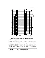
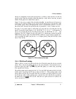
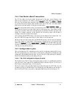
Figure 7-2 shows an example of the arbitration algorithm. Assume that several masters are
requesting use of the bus. If there are two masters in the high priority group and three in the
low priority group, then each high-priority master is guaranteed at least 1 out of 3
transaction slots, and each low-priority master is guaranteed 1 out of 9 transaction slots.
In Figure 7-2, the grant sequence (with all devices except device 4 requesting the bus and
device 3 being the current master) is 0, 2, MPC8240, 0, 2, 1, 0, 2, 3, … and repeating. If
device 2 is not requesting the bus, then the grant sequence is 0, MPC8240, 0, 1, 0, 3, … and
repeating. If device 2 requests the bus when device 0 is conducting a transaction and the
MPC8240 has the next grant, then the MPC8240 will have its grant removed and device 2
will be awarded the grant since device 2 is of higher priority than the MPC8240 when
device 0 has the bus.
Figure 7-2. PCI Arbitration Example
7.2.3 PCI Bus Parking
When no device is using or requesting the bus, the PCI arbiter grants the bus to a selected
device. This is known as parking the bus on the selected device. The selected device is
required to drive the AD[31:0], C/BE[0:3] and PAR signals to a stable value, preventing
these signals from floating.
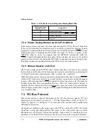
The parking mode control parameter (bits 14–13) in the PACR determines which device the
arbiter selects for parking the PCI bus as shown in Table 7-1. If the parking mode control
bits are 0b00 (or if the bus is not idle), then the bus is parked on the last master to use the
bus. If the bus is idle, and the parking mode control bits are b10, then the bus is parked on
the MPC8240; if the control bits are b01, then the bus is parked on device 0 (that is, the
device connected to GNT0).
Device 2
Device 0
Low
High Priority Group
Device 1
Device 3
Low Priority Group
(1/3)
(1/3)
(1/3)
(1/9)
(1/9)
(1/9)
priority
slot
MPC8240
Summary of Contents for MPC8240
Page 1: ...MPC8240UM D Rev 1 1 2001 MPC8240 Integrated Processor User s Manual ...
Page 38: ...xviii MPC8240 Integrated Processor User s Manual TABLES Table Number Title Page Number ...
Page 48: ...xlviii MPC8240 Integrated Processor User s Manual Acronyms and Abbreviations ...
Page 312: ...6 94 MPC8240 Integrated Processor User s Manual ROM Flash Interface Operation ...
Page 348: ...7 36 MPC8240 Integrated Processor User s Manual PCI Host and Agent Modes ...
Page 372: ...8 24 MPC8240 Integrated Processor User s Manual DMA Register Descriptions ...
Page 394: ...9 22 MPC8240 Integrated Processor User s Manual I2O Interface ...
Page 412: ...10 18 MPC8240 Integrated Processor User s Manual Programming Guidelines ...
Page 454: ...12 14 MPC8240 Integrated Processor User s Manual Internal Arbitration ...
Page 466: ...13 12 MPC8240 Integrated Processor User s Manual Exception Latencies ...
Page 516: ...16 14 Watchpoint Trigger Applications ...
Page 538: ...B 16 MPC8240 Integrated Processor User s Manual Setting the Endian Mode of Operation ...
Page 546: ...C 8 MPC8240 Integrated Processor User s Manual ...
Page 640: ...INDEX Index 16 MPC8240 Integrated Processor User s Manual ...

