Chapter 7. PCI Bus Interface
7-35
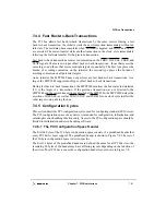
PCI Host and Agent Modes
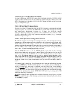
7.7.4.3 Initialization Code Translation in Agent Mode
Since the processor always vectors to 0xFFF0_0100 after a hard reset, it may be desirable
in some systems to fetch from an alternate or translated address space. This allows a system
designer to place the initialization code at some alternate system memory location such as
system main memory or alternate system ROM space. When configured for agent mode,
outbound PCI address translation is used to accomplish this task.
The MPC8240 has the flexibility of being programmable from a remote host controller. In
this case, the outbound translation window is set to map the local ROM space to an alternate
system address. The following procedure must be followed to take advantage of this
functionality:
1. MPC8240 is configured for agent mode, with ROM located in PCI memory space.
2. System performs a hard reset.
3. The MPC8240 processor core fetches the hard reset exception vector, which is
directed to the PCI bus. The transaction stalls and can not proceed until the PCI
command register master enable bit is enabled.
4. The system host controller initializes and configures the MPC8240 as an agent.
5. The host must program PCSRBAR to locate the EUMB within PCI memory space.
6. The host must set bit 1 of the PCI command register to enable MPC8240 response
to PCI memory accesses.
7. The host programs the outbound translation window to contain the ROM space and
the outbound translation base address to point to the location in system (PCI
memory) space where the initialization code resides.
8. The host then sets the PCI control register master enable bit in the MPC8240 to
allow the local processor reset vector fetch (stalled in step 3) to initiate a read from
the translated PCI location (as set up in step 7).
9. The MPC8240 then completes the pending reset exception fetch from the translated
system address and configures the local memory registers (described in Section 4.6,
“Memory Interface Configuration Registers”) and the inbound translation registers
(ITWR and LMBAR) as described in Section 3.3.3, “Address Translation
Registers.”
Summary of Contents for MPC8240
Page 1: ...MPC8240UM D Rev 1 1 2001 MPC8240 Integrated Processor User s Manual ...
Page 38: ...xviii MPC8240 Integrated Processor User s Manual TABLES Table Number Title Page Number ...
Page 48: ...xlviii MPC8240 Integrated Processor User s Manual Acronyms and Abbreviations ...
Page 312: ...6 94 MPC8240 Integrated Processor User s Manual ROM Flash Interface Operation ...
Page 348: ...7 36 MPC8240 Integrated Processor User s Manual PCI Host and Agent Modes ...
Page 372: ...8 24 MPC8240 Integrated Processor User s Manual DMA Register Descriptions ...
Page 394: ...9 22 MPC8240 Integrated Processor User s Manual I2O Interface ...
Page 412: ...10 18 MPC8240 Integrated Processor User s Manual Programming Guidelines ...
Page 454: ...12 14 MPC8240 Integrated Processor User s Manual Internal Arbitration ...
Page 466: ...13 12 MPC8240 Integrated Processor User s Manual Exception Latencies ...
Page 516: ...16 14 Watchpoint Trigger Applications ...
Page 538: ...B 16 MPC8240 Integrated Processor User s Manual Setting the Endian Mode of Operation ...
Page 546: ...C 8 MPC8240 Integrated Processor User s Manual ...
Page 640: ...INDEX Index 16 MPC8240 Integrated Processor User s Manual ...

