Chapter 11. Embedded Programmable Interrupt Controller (EPIC) Unit
11-11
EPIC Direct Interrupt Mode
11.5 EPIC Direct Interrupt Mode
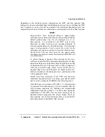
In direct interrupt mode, the IRQ[0:4] signals represent external interrupts that are
controlled and prioritized by the five IRQ vector/priority registers (IVPR0–IVPR4), and the
five IRQ destination registers (IDR0–IDR4). The external interrupts can be programmed
for either level- or edge-sensitive activation and either polarity. The direct interrupt mode
is selected when EICR[SIE]
=
0. Note that EICR[SIE] only has meaning when
GCR[M] = 1 (direct mode is a subset of mixed-mode operation).
11.6 EPIC Serial Interrupt Interface
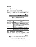
The serial interrupt mode is selected when EICR[SIE] = 1. Note that EICR[SIE] only has
meaning when GCR[M] = 1 (serial interrupt mode is also a subset of mixed-mode
operation). When the MPC8240 is in serial interrupt mode, 16 interrupt sources are
supported through the following serial interrupt signals (that are multiplexed with the
IRQ[0:3] input signals used in direct interrupt mode):
•
Serial interrupt (S_INT) input signal
•
Serial clock (S_CLK) output signal
•
Serial reset (S_RST) output signal
•
Serial frame (S_FRAME) output signal
The 16 serial interrupts are controlled and prioritized by the 16 serial vector/priority
registers (SVPR0–15) and the 16 serial destination registers (SDR0–15).
11.6.1 Sampling of Serial Interrupts
When the EPIC unit is programmed for serial interrupts, 16 sources are sampled through
the S_INT input signal. Each source (0–15) is allocated a one-cycle time slot in a sequence
of 16 cycles in which to request an interrupt. The serial interrupt interface is clocked by the
EPIC S_CLK output. This clock can be programmed to run at 1/2 to 1/14 of the MPC8240’s
SDRAM_CLK frequency by appropriately setting a 3-bit field in the serial interrupt
configuration register. See Section
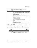
11.9.3, “EPIC Interrupt Configuration Register
(EICR).” Extreme care should be used with regard to board noise problems if a frequency
above 33 MHz is chosen. All references to the clock and to cycles in this subsection refer
to the S_CLK clock.
When EPIC is switched to serial mode by setting EICR[SIE] = 1, a 16-cycle sequence
begins 4 S_CLK cycles after EPIC outputs a 2-cycle high pulse through the S_RST output
signal. The 16-cycle sequence keeps repeating; after going from interrupt source cycle
count of 0, 1, 2, 3, 4,... 15, the count immediately returns to 0, 1, 2, and so on, with no
S_CLK delays between cycle count 15 and the next cycle count 0. Each time the sequence
count is pointing to interrupt source 0, the S_FRAME signal is active. S_FRAME is
provided to guarantee synchronization between the MPC8240’s EPIC unit and the serial
interrupt source device.
Summary of Contents for MPC8240
Page 1: ...MPC8240UM D Rev 1 1 2001 MPC8240 Integrated Processor User s Manual ...
Page 38: ...xviii MPC8240 Integrated Processor User s Manual TABLES Table Number Title Page Number ...
Page 48: ...xlviii MPC8240 Integrated Processor User s Manual Acronyms and Abbreviations ...
Page 312: ...6 94 MPC8240 Integrated Processor User s Manual ROM Flash Interface Operation ...
Page 348: ...7 36 MPC8240 Integrated Processor User s Manual PCI Host and Agent Modes ...
Page 372: ...8 24 MPC8240 Integrated Processor User s Manual DMA Register Descriptions ...
Page 394: ...9 22 MPC8240 Integrated Processor User s Manual I2O Interface ...
Page 412: ...10 18 MPC8240 Integrated Processor User s Manual Programming Guidelines ...
Page 454: ...12 14 MPC8240 Integrated Processor User s Manual Internal Arbitration ...
Page 466: ...13 12 MPC8240 Integrated Processor User s Manual Exception Latencies ...
Page 516: ...16 14 Watchpoint Trigger Applications ...
Page 538: ...B 16 MPC8240 Integrated Processor User s Manual Setting the Endian Mode of Operation ...
Page 546: ...C 8 MPC8240 Integrated Processor User s Manual ...
Page 640: ...INDEX Index 16 MPC8240 Integrated Processor User s Manual ...


