16-12
State and Block Diagrams
16.3 State and Block Diagrams
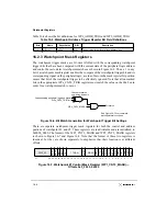
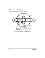
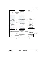
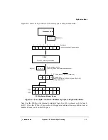
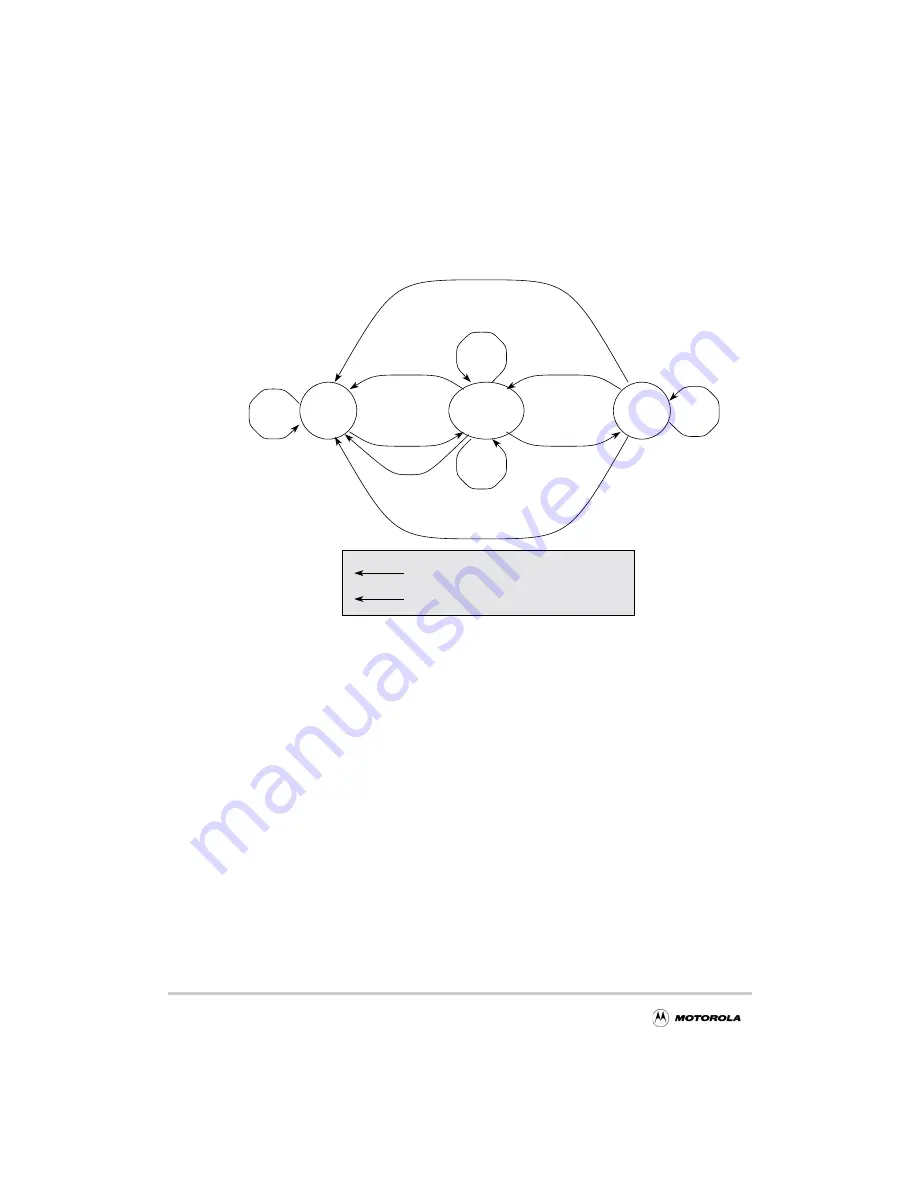
Figure 16-12 shows a state diagram of the watchpoint facility.
Figure 16-12. Watchpoint Facility State Diagram
COMPARE
IDLE
HOLD
wp_run
!wp_run
match &
!match
!resume
match &
resume &
!wp_cont &
match &
wp_cont &
wp_trig_hold
!wp_cont
!wp_trig_hold
!wp_trig_hold
resume &
wp_cont
1
1
1
1
0
0
0
0
0
0
Output trigger, TRIG_OUT, is inactive.
1
Output trigger, TRIG_OUT, is active.
!wp_run
0
!wp_run
0
Summary of Contents for MPC8240
Page 1: ...MPC8240UM D Rev 1 1 2001 MPC8240 Integrated Processor User s Manual ...
Page 38: ...xviii MPC8240 Integrated Processor User s Manual TABLES Table Number Title Page Number ...
Page 48: ...xlviii MPC8240 Integrated Processor User s Manual Acronyms and Abbreviations ...
Page 312: ...6 94 MPC8240 Integrated Processor User s Manual ROM Flash Interface Operation ...
Page 348: ...7 36 MPC8240 Integrated Processor User s Manual PCI Host and Agent Modes ...
Page 372: ...8 24 MPC8240 Integrated Processor User s Manual DMA Register Descriptions ...
Page 394: ...9 22 MPC8240 Integrated Processor User s Manual I2O Interface ...
Page 412: ...10 18 MPC8240 Integrated Processor User s Manual Programming Guidelines ...
Page 454: ...12 14 MPC8240 Integrated Processor User s Manual Internal Arbitration ...
Page 466: ...13 12 MPC8240 Integrated Processor User s Manual Exception Latencies ...
Page 516: ...16 14 Watchpoint Trigger Applications ...
Page 538: ...B 16 MPC8240 Integrated Processor User s Manual Setting the Endian Mode of Operation ...
Page 546: ...C 8 MPC8240 Integrated Processor User s Manual ...
Page 640: ...INDEX Index 16 MPC8240 Integrated Processor User s Manual ...

