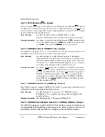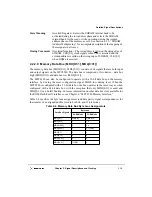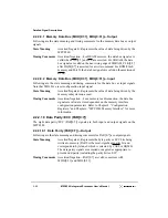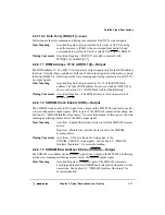
2-6
MPC8240 Integrated Processor User’s Manual
Signal Overview
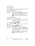
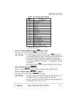
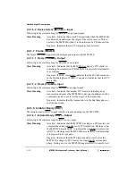
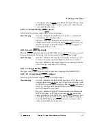
2.1.2 Output Signal States during Reset
When a system reset is recognized (assertion of HRST_CPU and HRST_CTRL), the
MPC8240 aborts all current internal and external transactions, and releases all bidirectional
I/O signals to a high-impedance state. See Section 13.2.1, “System Reset,” for a complete
description of the reset functionality.
There are 19 signals that serve alternate functions as reset configuration input signals
during system reset. Their default values and the interpretation of their voltage levels during
reset are described in Section 2.4, “Configuration Signals Sampled at Reset.”
SDMA12
SDRAM address 12
Memory
1
O
SDMA[11:0]
SDRAM address 11–0
Memory
12
O
SDRAM_CLK[0:3]
SDRAM clock outputs
Clock
—
4
O
SDRAM_SYNC_OUT
SDRAM clock output
Clock
—
1
O
SDRAM_SYNC_IN
SDRAM feedback clock
Clock
—
1
I
SDRAS
SDRAM row address
strobe
Memory
—
1
O
SERR
System error
PCI
—
1
I/O
S_FRAME
Serial interrupt frame
EPIC Control
IRQ3
1
I/O
S_INT
Serial interrupt stream
EPIC Control
IRQ0
1
I
SMI
System management
interrupt
System Control
—
1
I
S_RST
Serial interrupt reset
EPIC Control
IRQ2
1
I/O
SRESET
Soft reset
System Control
—
1
I
STOP
Stop
PCI
—
1
I/O
TBEN
Time base enable
System Control
—
1
I
TCK
JTAG test clock
Test
—
1
I
TDO
JTAG test data output
Test
—
1
O
TDI
JTAG test data Input
Test
—
1
I
TMS
JTAG test mode select
Test
—
1
I
TRDY
Target ready
PCI
—
1
I/O
TRIG_IN
Watchpoint trigger in
System Control
1
I
TRIG_OUT
Watchpoint trigger out
System Control
1
O
TRST
JTAG test reset
Test
—
1
I
WE
Write enable
Memory
—
1
O
1
The MPC8240 samples these signals at the negation of reset to determine the reset configuration. After they
are sampled, they assume their normal functions. See Section 2.4, “Configuration Signals Sampled at Reset,”
for more information about their function during reset.
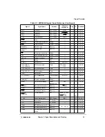
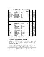
Table 2-1. MPC8240 Signal Cross Reference (Continued)
Signal
Signal Name
Interface
Alternate
Function (s)
Pins
I/O
Section #
Summary of Contents for MPC8240
Page 1: ...MPC8240UM D Rev 1 1 2001 MPC8240 Integrated Processor User s Manual ...
Page 38: ...xviii MPC8240 Integrated Processor User s Manual TABLES Table Number Title Page Number ...
Page 48: ...xlviii MPC8240 Integrated Processor User s Manual Acronyms and Abbreviations ...
Page 312: ...6 94 MPC8240 Integrated Processor User s Manual ROM Flash Interface Operation ...
Page 348: ...7 36 MPC8240 Integrated Processor User s Manual PCI Host and Agent Modes ...
Page 372: ...8 24 MPC8240 Integrated Processor User s Manual DMA Register Descriptions ...
Page 394: ...9 22 MPC8240 Integrated Processor User s Manual I2O Interface ...
Page 412: ...10 18 MPC8240 Integrated Processor User s Manual Programming Guidelines ...
Page 454: ...12 14 MPC8240 Integrated Processor User s Manual Internal Arbitration ...
Page 466: ...13 12 MPC8240 Integrated Processor User s Manual Exception Latencies ...
Page 516: ...16 14 Watchpoint Trigger Applications ...
Page 538: ...B 16 MPC8240 Integrated Processor User s Manual Setting the Endian Mode of Operation ...
Page 546: ...C 8 MPC8240 Integrated Processor User s Manual ...
Page 640: ...INDEX Index 16 MPC8240 Integrated Processor User s Manual ...


