Chapter 4. Configuration Registers
4-23
Memory Interface Configuration Registers
4.6 Memory Interface Configuration Registers
The memory interface configuration registers (MICRs) control memory boundaries
(starting and ending addresses), memory bank enables, memory timing, and external
memory buffers. Initialization software must program the MICRs at reset and then enable
the memory interface on the MPC8240 by setting the MEMGO bit in memory control
configuration register 1 (MCCR1).
4.6.1 Memory Boundary Registers
The extended starting address and the starting address registers are used to define the lower
address boundary for each memory bank. The lower boundary is determined by the
following formula:
Lower boundary for bank n = 0b00 || <extended starting address n> || <starting address n>
|| 0x0_0000.
The extended ending address and the ending address registers are used to define the upper
address boundary for each memory bank. The upper boundary is determined by the
following formula:
Upper boundary for bank n = 0b00 || <extended ending address n> || <ending address n> ||
0xF_FFFF.
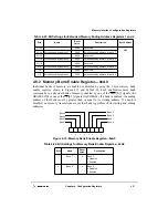
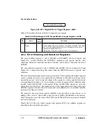
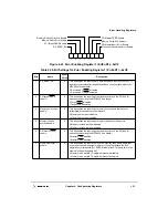
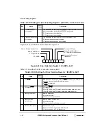
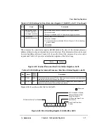
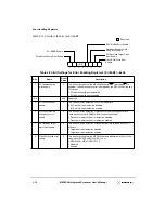
Figure 4-7, Figure 4-8, and Table 4-20 depict the memory starting address register 1 and 2
bit settings.
Figure 4-7. Memory Starting Address Register 1—0x80
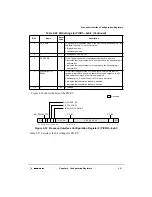
Table 4-19. Embedded Utilities Memory Base Address Register—0x78
Bits Name
Reset
Value
Description
msb
31–20
Base Address
0x000
Base address of the embedded memory utilities block. The block size is 1 Mbyte,
and its base address is aligned naturally to a 1 Mbyte address boundary (so the
base address is 0xXXX0_0000). This block is used by processor-initiated
transactions and should be located within PCI memory space.
Registers within the EUMB are located from 0x8000_0000 to 0xFDFF_FFFF
.
Thus, valid values are 0x800–0xFDF. Otherwise, the EUMB is effectively disabled.
19–0
—
0x0_0000
Reserved
Starting Address Bank 3 Starting Address Bank 2 Starting Address Bank 1 Starting Address Bank 0
31
24 23
16 15
8
7
0
Summary of Contents for MPC8240
Page 1: ...MPC8240UM D Rev 1 1 2001 MPC8240 Integrated Processor User s Manual ...
Page 38: ...xviii MPC8240 Integrated Processor User s Manual TABLES Table Number Title Page Number ...
Page 48: ...xlviii MPC8240 Integrated Processor User s Manual Acronyms and Abbreviations ...
Page 312: ...6 94 MPC8240 Integrated Processor User s Manual ROM Flash Interface Operation ...
Page 348: ...7 36 MPC8240 Integrated Processor User s Manual PCI Host and Agent Modes ...
Page 372: ...8 24 MPC8240 Integrated Processor User s Manual DMA Register Descriptions ...
Page 394: ...9 22 MPC8240 Integrated Processor User s Manual I2O Interface ...
Page 412: ...10 18 MPC8240 Integrated Processor User s Manual Programming Guidelines ...
Page 454: ...12 14 MPC8240 Integrated Processor User s Manual Internal Arbitration ...
Page 466: ...13 12 MPC8240 Integrated Processor User s Manual Exception Latencies ...
Page 516: ...16 14 Watchpoint Trigger Applications ...
Page 538: ...B 16 MPC8240 Integrated Processor User s Manual Setting the Endian Mode of Operation ...
Page 546: ...C 8 MPC8240 Integrated Processor User s Manual ...
Page 640: ...INDEX Index 16 MPC8240 Integrated Processor User s Manual ...


