4-34
MPC8240 Integrated Processor User’s Manual
Error Handling Registers
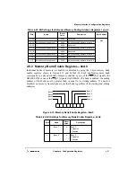
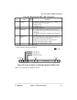
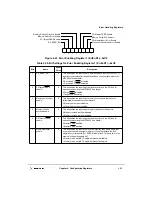
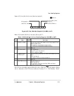
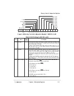
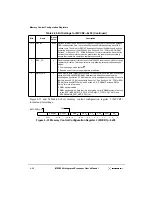
Figure 4-20. ECC Single-Bit Error Trigger Register—0xB9
Table 4-29 describes the bits of the ECC single-bit error trigger.
4.8.2 Error Enabling and Detection Registers
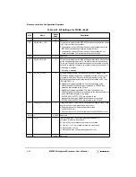
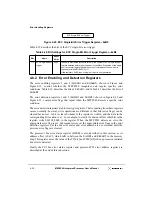
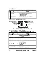
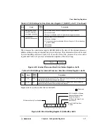
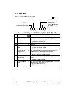
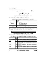
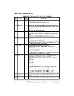
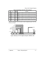
The error enabling registers 1 and 2 (ErrEnR1 and ErrEnR2), shown in Figure and
Figure 4-24, control whether the MPC8240 recognizes and reports specific error
conditions. Table 4-30 describes the bits of ErrEnR1, and Table 4-33 describes the bits of
ErrEnR2.
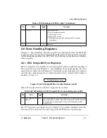
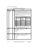
The error detection registers 1 and 2 (ErrDR1 and ErrDR2), shown in Figure 4-22 and
Figure 4-25, contain error flags that report when the MPC8240 detects a specific error
condition.
The error detection registers are bit-reset type registers. That is, reading from these registers
occurs normally; however, write operations are different in that bits (error flags) can be
cleared but not set. A bit is cleared whenever the register is written, and the data in the
corresponding bit location is a 1. For example, to clear bit 6 and not affect other bits in the
register, write 0b0100_0000 to the register. When the MPC8240 detects an error, the
appropriate error flag is set. Subsequent errors set the appropriate error flags in the error
detection registers, but the bus error status and error address are not recorded until the
previous error flags are cleared.
The processor bus error status register (BESR) is also described in this section, as its
address offset is 0xC3, which falls in between the ErrDR1 and ErrEnR2 in the memory
map. This register saves the value of the TT[0:4] and TSIZ[0:2] when a processor-initiated
bus error is detected.
Finally the PCI bus error status register and processor/PCI error address register are
described at the end of this subsection.
Table 4-29. Bit Settings for ECC Single-Bit Error Trigger Register—0xB9
Bits
Name
Reset
Value
Description
7–0
ECC single-bit error
trigger
All 0s
These bits provide the threshold value for the number of ECC single-bit errors
that are detected before reporting an error condition. If the value of the single
bit error counter register equals the value of this register, then an error is
reported (provided ErrEnR1[2] = 1).
If this register = 0x00, then no single bit error is ever generated.
ECC Single-Bit Error Trigger
7
0
Summary of Contents for MPC8240
Page 1: ...MPC8240UM D Rev 1 1 2001 MPC8240 Integrated Processor User s Manual ...
Page 38: ...xviii MPC8240 Integrated Processor User s Manual TABLES Table Number Title Page Number ...
Page 48: ...xlviii MPC8240 Integrated Processor User s Manual Acronyms and Abbreviations ...
Page 312: ...6 94 MPC8240 Integrated Processor User s Manual ROM Flash Interface Operation ...
Page 348: ...7 36 MPC8240 Integrated Processor User s Manual PCI Host and Agent Modes ...
Page 372: ...8 24 MPC8240 Integrated Processor User s Manual DMA Register Descriptions ...
Page 394: ...9 22 MPC8240 Integrated Processor User s Manual I2O Interface ...
Page 412: ...10 18 MPC8240 Integrated Processor User s Manual Programming Guidelines ...
Page 454: ...12 14 MPC8240 Integrated Processor User s Manual Internal Arbitration ...
Page 466: ...13 12 MPC8240 Integrated Processor User s Manual Exception Latencies ...
Page 516: ...16 14 Watchpoint Trigger Applications ...
Page 538: ...B 16 MPC8240 Integrated Processor User s Manual Setting the Endian Mode of Operation ...
Page 546: ...C 8 MPC8240 Integrated Processor User s Manual ...
Page 640: ...INDEX Index 16 MPC8240 Integrated Processor User s Manual ...


