Chapter 7. PCI Bus Interface
7-19
PCI Bus Transactions
As a target, the MPC8240 terminates a transaction with a target disconnect due to the
following:
•
It is unable to respond within eight PCI clock cycles (not including the first data
phase).
•
A cache line (32 bytes) of data is transferred for a cache-wrap mode read transaction.
(See the discussion of cache wrap mode in Section 7.3.3.1, “Memory Space
Addressing,” for more information.)
•
A single beat of data is transferred for a cache-wrap mode write transaction. (See the
discussion of cache wrap mode in Section 7.3.3.1, “Memory Space Addressing,” for
more information.)
•
The last four bytes of a cache line are transferred in linear-incrementing address
mode. (See the description of linear-incrementing mode in Section 7.3.3.1,
“Memory Space Addressing,” for more information.)
•
If AD[1:0] = 0b01 or AD[1:0] = 0b11 during the address phase of a local memory
access. (See Section 7.3.3.1, “Memory Space Addressing,” for more information.)
As a target, the MPC8240 responds to a transaction with a retry due to the following:
•
A processor copyback operation is in progress.
•
A PCI write to local memory was attempted when the internal
PCI-to-local-memory-write buffers (PCMWBs) are full.
•
A nonexclusive access was attempted to local memory while the MPC8240 was
locked.
•
A configuration write to a PCI device is underway and
PICR2[NO_SERIAL_CFG] = 0.
•
An access to one of the MPC8240 internal configuration registers is in progress.
•
The 16-clock latency timer has expired, and the first data phase has not begun.
As a target, the MPC8240 responds with a target-abort if a PCI master attempts to write to
the ROM/Flash ROM space in address map B. For PCI writes to local memory, if an address
parity error or data parity error occurs, the MPC8240 aborts the transaction internally but
continues the transaction on the PCI bus.
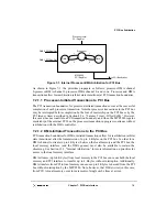
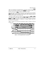
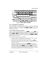
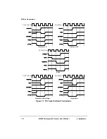
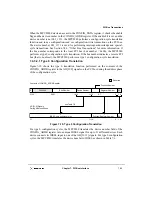
Figure 7-7 shows several target-initiated terminations. The three disconnect terminations
are unique in the data transferred at the end of the transaction. For Disconnect A, the
initiator is negating IRDY when the target asserts STOP and data is transferred only at the
end of the current data phase. For Disconnect B, the target negates TRDY one clock after
it asserts STOP, indicating that the target can accept the current data, but no more data can
be transferred. For the Disconnect-without-data, the target asserts STOP when TRDY is
negated indicating that the target cannot accept any more data.
Summary of Contents for MPC8240
Page 1: ...MPC8240UM D Rev 1 1 2001 MPC8240 Integrated Processor User s Manual ...
Page 38: ...xviii MPC8240 Integrated Processor User s Manual TABLES Table Number Title Page Number ...
Page 48: ...xlviii MPC8240 Integrated Processor User s Manual Acronyms and Abbreviations ...
Page 312: ...6 94 MPC8240 Integrated Processor User s Manual ROM Flash Interface Operation ...
Page 348: ...7 36 MPC8240 Integrated Processor User s Manual PCI Host and Agent Modes ...
Page 372: ...8 24 MPC8240 Integrated Processor User s Manual DMA Register Descriptions ...
Page 394: ...9 22 MPC8240 Integrated Processor User s Manual I2O Interface ...
Page 412: ...10 18 MPC8240 Integrated Processor User s Manual Programming Guidelines ...
Page 454: ...12 14 MPC8240 Integrated Processor User s Manual Internal Arbitration ...
Page 466: ...13 12 MPC8240 Integrated Processor User s Manual Exception Latencies ...
Page 516: ...16 14 Watchpoint Trigger Applications ...
Page 538: ...B 16 MPC8240 Integrated Processor User s Manual Setting the Endian Mode of Operation ...
Page 546: ...C 8 MPC8240 Integrated Processor User s Manual ...
Page 640: ...INDEX Index 16 MPC8240 Integrated Processor User s Manual ...

