7-32
MPC8240 Integrated Processor User’s Manual
PCI Host and Agent Modes
7.6.2 Error Reporting
PCI provides for the detection and signaling of both parity and other system errors. Two
signals are used to report these errors—PERR and SERR. The PERR signal is used
exclusively to report data parity errors on all transactions except special cycles. The SERR
signal is used for other error signaling including address parity errors and data parity errors
on special-cycle transactions; it may also be used to signal other system errors. Refer to
Section 13.3.3, “PCI Interface Errors,” for a complete description of MPC8240 actions due
to parity and other errors.
7.7 PCI Host and Agent Modes
This section describes the different modes available in the MPC8240.
The MPC8240 can function as either a PCI host bridge (referred to as ‘host mode’) or a
peripheral device on the PCI bus (referred to as ‘agent mode’). The MAA1 configuration
signal, sampled at reset, configures the MPC8240 for host or agent mode as described in
Section 2.4, “Configuration Signals Sampled at Reset.” Note that agent mode is supported
only for address map B. It is a configuration error to set the MPC8240 to use address map
A and agent mode. Also note that in agent mode, the MPC8240 ignores all PCI memory
accesses (except to the EUMB) until inbound address translation is enabled. See
Section 7.7.4.1, “Inbound PCI Address Translation,” and Section 3.3.1, “Inbound PCI
Address Translation,” for more information about inbound address translation.
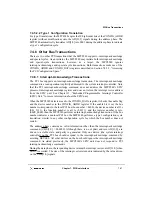
7.7.1 PCI Initialization Options
The assertion of the HRST_CPU and HRST_CTRL signals (must be asserted together)
cause the processor to take a hard reset exception. The physical address of the handler is
always 0xFFF0_0100. Host and agent modes provide different options for initial reset
exception vector fetching, and register configuration.
When the MPC8240 is configured for host mode, the system may initialize by fetching
initial instructions from a ROM/Flash device. The setting of the RCS0 configuration signal
at the negation of the reset signals determines whether ROM/Flash is located in local
memory space or in PCI memory space. See Section 2.4, “Configuration Signals Sampled
at Reset,” for more information.
When the MPC8240 is configured for agent mode, it can also be configured to initialize
from local memory space or remote PCI memory space.
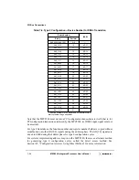
Table 7-8 summarizes the initialization modes of the MPC8240. The initial settings of the
PCI command register bus master and memory space bits (bits 2 and 1, respectively) are
determined based on the reset configuration signals as shown in the table.
Summary of Contents for MPC8240
Page 1: ...MPC8240UM D Rev 1 1 2001 MPC8240 Integrated Processor User s Manual ...
Page 38: ...xviii MPC8240 Integrated Processor User s Manual TABLES Table Number Title Page Number ...
Page 48: ...xlviii MPC8240 Integrated Processor User s Manual Acronyms and Abbreviations ...
Page 312: ...6 94 MPC8240 Integrated Processor User s Manual ROM Flash Interface Operation ...
Page 348: ...7 36 MPC8240 Integrated Processor User s Manual PCI Host and Agent Modes ...
Page 372: ...8 24 MPC8240 Integrated Processor User s Manual DMA Register Descriptions ...
Page 394: ...9 22 MPC8240 Integrated Processor User s Manual I2O Interface ...
Page 412: ...10 18 MPC8240 Integrated Processor User s Manual Programming Guidelines ...
Page 454: ...12 14 MPC8240 Integrated Processor User s Manual Internal Arbitration ...
Page 466: ...13 12 MPC8240 Integrated Processor User s Manual Exception Latencies ...
Page 516: ...16 14 Watchpoint Trigger Applications ...
Page 538: ...B 16 MPC8240 Integrated Processor User s Manual Setting the Endian Mode of Operation ...
Page 546: ...C 8 MPC8240 Integrated Processor User s Manual ...
Page 640: ...INDEX Index 16 MPC8240 Integrated Processor User s Manual ...

