


Chapter 9. Message Unit (with I
2
O)
9-5
I
2
O Interface
9.3 I
2
O Interface
The intelligent input output (I
2
O) specification was established in the industry to allow
architecture-independent I/O subsystems to communicate with an OS through an
abstraction layer. The specification is centered around a message-passing scheme. An
I
2
O-compliant embedded peripheral (IOP) is comprised of memory, processor, and
input/output devices. The IOP dedicates a certain space in its local memory to hold inbound
(from the remote processor) and outbound (to the remote processor) messages. The space
is managed as memory-mapped FIFOs with pointers to this memory maintained through
the MPC8240 I
2
O registers.
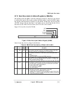
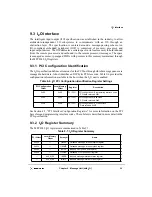
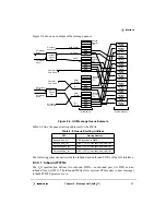
9.3.1 PCI Configuration Identification
The I
2
O specification defines extensions for the PCI bus through which message queues are
managed in hardware. A host identifies an IOP by its PCI class code. Table 9-6 provides the
configuration information available to the host when the I
2
O unit is enabled.
See Section 4.2, “PCI Interface Configuration Registers,” for more information on the PCI
base class and programming interface codes. The subclass is described in more detail in the
PCI specification.
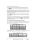
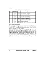
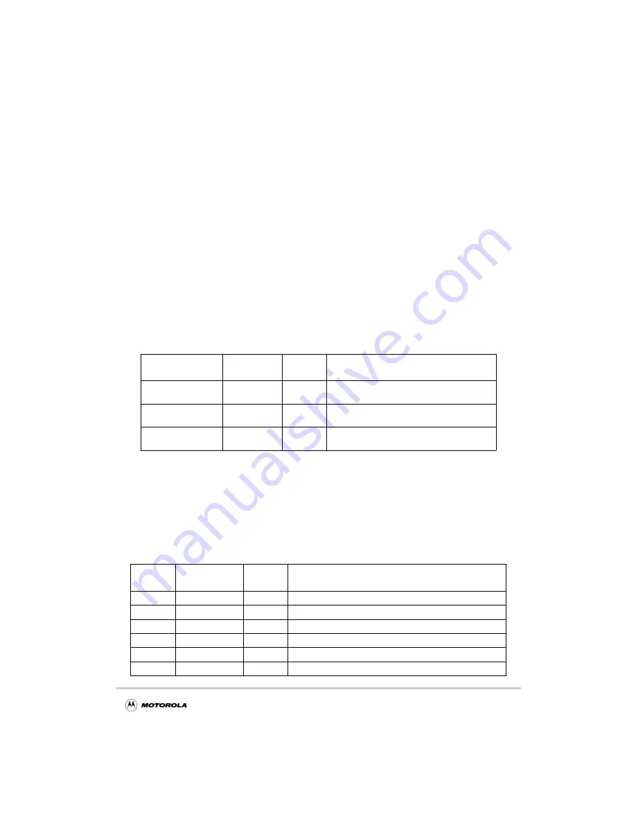
9.3.2 I
2
O Register Summary
The MPC8240 I
2
O registers are summarized in Table 9-7.
Table 9-6. I
2
O PCI Configuration Identification Register Settings
PCI Configuration
Offset
Local Memory
Offset
Register
Description
0x09
0x09
PCI CFG
PCI configuration—Programming interface code
PCI data returned: 0x01
0x0A
0x0A
PCI CFG
PCI configuration—Sub class
PCI data returned: 0x00
0x0B
0x0B
PCI CFG
PCI configuration—PCI base class
Data returned: 0x0E
Table 9-7. I
2
O Register Summary
PCI Offset
Local Memory
Offset
Acronym
Name
0x030
—
OMISR
Outbound message interrupt status register
0x034
—
OMIMR
Outbound message interrupt mask register
0x040
—
IFQPR
Inbound FIFO queue port register
0x044
—
OFQPR
Outbound FIFO queue port register
—
0x0_0100
IMISR
Inbound message interrupt status register
—
0x0_0104
IMIMR
Inbound message interrupt mask register
Summary of Contents for MPC8240
Page 1: ...MPC8240UM D Rev 1 1 2001 MPC8240 Integrated Processor User s Manual ...
Page 38: ...xviii MPC8240 Integrated Processor User s Manual TABLES Table Number Title Page Number ...
Page 48: ...xlviii MPC8240 Integrated Processor User s Manual Acronyms and Abbreviations ...
Page 312: ...6 94 MPC8240 Integrated Processor User s Manual ROM Flash Interface Operation ...
Page 348: ...7 36 MPC8240 Integrated Processor User s Manual PCI Host and Agent Modes ...
Page 372: ...8 24 MPC8240 Integrated Processor User s Manual DMA Register Descriptions ...
Page 394: ...9 22 MPC8240 Integrated Processor User s Manual I2O Interface ...
Page 412: ...10 18 MPC8240 Integrated Processor User s Manual Programming Guidelines ...
Page 454: ...12 14 MPC8240 Integrated Processor User s Manual Internal Arbitration ...
Page 466: ...13 12 MPC8240 Integrated Processor User s Manual Exception Latencies ...
Page 516: ...16 14 Watchpoint Trigger Applications ...
Page 538: ...B 16 MPC8240 Integrated Processor User s Manual Setting the Endian Mode of Operation ...
Page 546: ...C 8 MPC8240 Integrated Processor User s Manual ...
Page 640: ...INDEX Index 16 MPC8240 Integrated Processor User s Manual ...


