Chapter 15. Debug Features
15-19
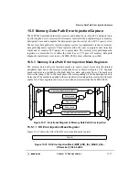
Memory Data Path Error Injection/Capture
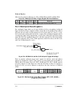
15.5.2 Memory Data Path Error Capture Monitor Registers
The memory data-path error capture monitors are used to latch data that causes ECC or
parity errors from either the internal peripheral logic bus or the memory data/parity bus.
Separate monitors are provided for the high data, low data, and parity buses. The monitors
are read-only. They are loaded automatically when the error detection registers detect any
of the following:
•
A memory read parity error / single-bit ECC error trigger exceeded; EDR1[2]
•
A multi-bit ECC error; EDR2[3]
•
A write parity error; EDR2[2]
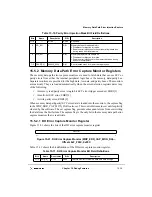
When memory data path parity/ECC error data is loaded into the monitors, the capture flag
in the MDP_ERR_CAP_MON_PAR is also set. This control bit remains set until explicitly
cleared by the software. The set capture flag prevents subsequent errors from overwriting
the data from the first failure. The capture flag is the only bit in the memory data path error
capture monitors that is read/write.
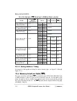
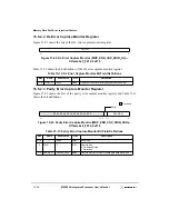
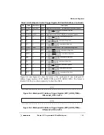
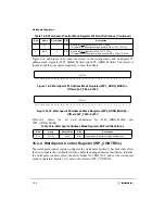
15.5.2.1 DH Error Capture Monitor Register
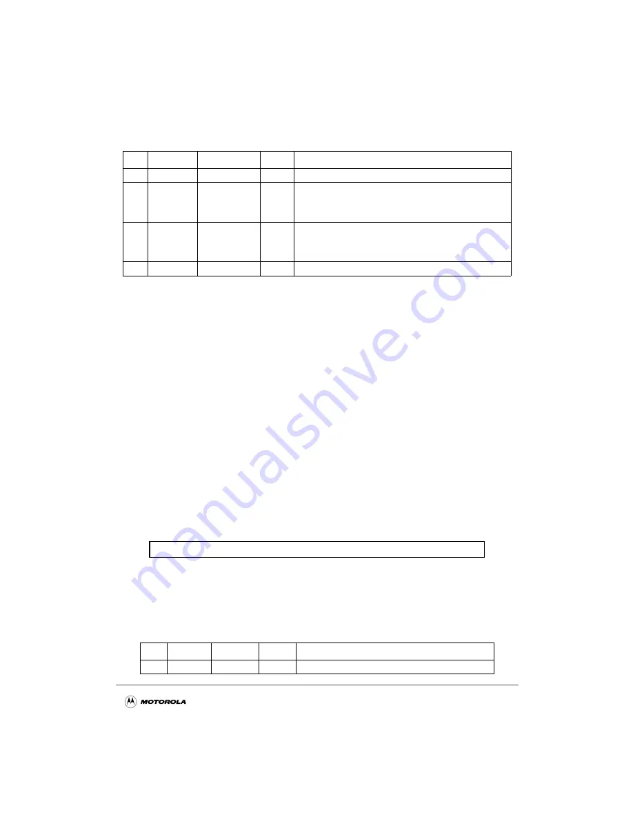
Figure 15-21 shows the bits of the DH error capture monitor register.
Figure 15-21. DH Error Capture Monitor (MDP_ERR_CAP_MON_DH)—
Offsets 0xF_F00C, 0xF0C
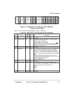
Table 15-11 shows the bit definitions of the DH error capture monitor register.
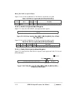
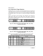
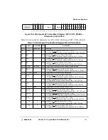
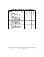
Table 15-10. Parity Error Injection Mask Bit Field Definitions
Bits
Name
Reset Value
R/W
Description
31–8
—
all 0s
Read
Reserved
9
RD_EN
0
R/W
Memory data path read enable bit
0 Disables error injection for reads
1 Enables error injection onto the peripheral logic data bus
during reads from local memory
8
WR_EN
0
R/W
Memory data path write enable bit
0 Disables error injection for writes
1 Enables error injection onto the memory data bus during
writes to local memory
7–0
DPAR[7:0]
0b0000_0000
R/W
Error injection mask for memory data parity bus
Table 15-11. DH Error Capture Monitor Bit Field Definitions
Bits
Name
Reset Value
R/W
Description
31–0
DH[31:0]
all 0s
Read
Capture monitor for memory data path data bus high
DH[31:0]
31
0
Summary of Contents for MPC8240
Page 1: ...MPC8240UM D Rev 1 1 2001 MPC8240 Integrated Processor User s Manual ...
Page 38: ...xviii MPC8240 Integrated Processor User s Manual TABLES Table Number Title Page Number ...
Page 48: ...xlviii MPC8240 Integrated Processor User s Manual Acronyms and Abbreviations ...
Page 312: ...6 94 MPC8240 Integrated Processor User s Manual ROM Flash Interface Operation ...
Page 348: ...7 36 MPC8240 Integrated Processor User s Manual PCI Host and Agent Modes ...
Page 372: ...8 24 MPC8240 Integrated Processor User s Manual DMA Register Descriptions ...
Page 394: ...9 22 MPC8240 Integrated Processor User s Manual I2O Interface ...
Page 412: ...10 18 MPC8240 Integrated Processor User s Manual Programming Guidelines ...
Page 454: ...12 14 MPC8240 Integrated Processor User s Manual Internal Arbitration ...
Page 466: ...13 12 MPC8240 Integrated Processor User s Manual Exception Latencies ...
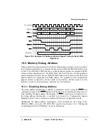
Page 516: ...16 14 Watchpoint Trigger Applications ...
Page 538: ...B 16 MPC8240 Integrated Processor User s Manual Setting the Endian Mode of Operation ...
Page 546: ...C 8 MPC8240 Integrated Processor User s Manual ...
Page 640: ...INDEX Index 16 MPC8240 Integrated Processor User s Manual ...


