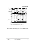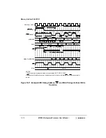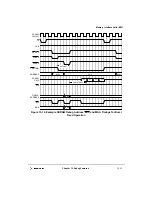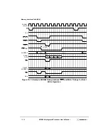
Chapter 16. Programmable I/O and Watchpoint
16-3
Watchpoint Registers
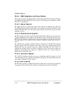
16.2 Watchpoint Registers
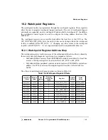
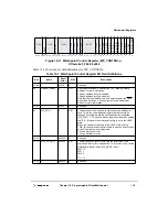
The watchpoint facility is programmed through the watchpoint registers. These registers
allow the user to program watchpoint triggers and masks. Two sets of watchpoint triggers
and masks are supported, one for watchpoint #1 and another for watchpoint #2. In addition,
the watchpoint control register is used to configure the debug address function of the
MPC8240
The watchpoint registers are accessible from either the local bus or the PCI bus. The
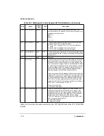
WP_CONTROL[WP_RUN] bit is the only bit that can be changed while the watchpoint
facility is enabled (while WP_RUN = 1). Changing any other values in the watchpoint
registers while WP_RUN = 1 is not supported and results in unpredictable behavior.
16.2.1 Watchpoint
Register Address Map
The watchpoint registers reside in an area of the embedded utilities block that is shared by
the memory data path diagnostic registers and are mapped as follows:
•
Embedded utilities memory block (EUMBBAR contains base address) for local bus
accesses. Watchpoint registers located at offsets 0xF_F018 to 0xF_F048.
•
Embedded utilities peripheral control and status registers (PCSRBAR contains base
address) for PCI bus accesses. Watchpoint registers located at offsets 0xF18 to
0xF48.
The offsets to individual watchpoint registers are listed in Table 16-2.
Table 16-2. Watchpoint Register Offsets
Local Bus
Offset
PCI Bus
Offset
Size
(bytes)
Program
Access Size
(bytes)
Register
Register
Access
Reset
Value
0xF_F018
0xF18
4 4
WP1_CNTL_TRIG
R/W
0x0000_0000
0xF_F01C’
0xF1C
4 4
WP1_ADDR_TRIG
R/W
0x0000_0000
0xF_F020
0xF20
4 4
WP1_CTRL_MASK
R/W
0x0000_0000
0xF_F024
0xF24
4 4
WP1_ADDR_MASK
R/W
0x0000_0000
0xF_F030
0xF30
4 4
WP2_CNTL_TRIG
R/W
0x0000_0000
0xF_F034
0xF34
4
4
WP2_ADDR_TRIG
R/W
0x0000_0000
0xF_F038
0xF38
4
4
WP2_CTRL_MASK
R/W
0x0000_0000
0xF_F03C
0xF3C
4
4
WP2_ADDR_MASK
R/W
0x0000_0000
0xF_F048
0xF48
4
1-, 2-, or 4-
WP_CONTROL
R/W
0x1000_0000
Summary of Contents for MPC8240
Page 1: ...MPC8240UM D Rev 1 1 2001 MPC8240 Integrated Processor User s Manual ...
Page 38: ...xviii MPC8240 Integrated Processor User s Manual TABLES Table Number Title Page Number ...
Page 48: ...xlviii MPC8240 Integrated Processor User s Manual Acronyms and Abbreviations ...
Page 312: ...6 94 MPC8240 Integrated Processor User s Manual ROM Flash Interface Operation ...
Page 348: ...7 36 MPC8240 Integrated Processor User s Manual PCI Host and Agent Modes ...
Page 372: ...8 24 MPC8240 Integrated Processor User s Manual DMA Register Descriptions ...
Page 394: ...9 22 MPC8240 Integrated Processor User s Manual I2O Interface ...
Page 412: ...10 18 MPC8240 Integrated Processor User s Manual Programming Guidelines ...
Page 454: ...12 14 MPC8240 Integrated Processor User s Manual Internal Arbitration ...
Page 466: ...13 12 MPC8240 Integrated Processor User s Manual Exception Latencies ...
Page 516: ...16 14 Watchpoint Trigger Applications ...
Page 538: ...B 16 MPC8240 Integrated Processor User s Manual Setting the Endian Mode of Operation ...
Page 546: ...C 8 MPC8240 Integrated Processor User s Manual ...
Page 640: ...INDEX Index 16 MPC8240 Integrated Processor User s Manual ...

