4-2
MPC8260 PowerQUICC II UserÕs Manual
MOTOROLA
Part II. ConÞguration and Reset
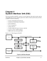
The system conÞguration and protection functions provide various monitors and timers,
including the bus monitor, software watchdog timer, periodic interrupt timer, and time
counter. The clock synthesizer generates the clock signals used by the SIU and other
MPC8260 modules. The SIU clocking scheme supports stop and normal modes.
The 60x bus interface is a standard pipelined bus. The MPC8260 allows external bus
masters to request and obtain system bus mastership. Chapter 8, ÒThe 60x Bus,Ó describes
bus operation, but 60x bus conÞguration is explained in this section.
The memory controller module, described in Chapter 10, ÒMemory Controller,Ó provides a
seamless interface to many types of memory devices and peripherals. It supports up to
twelve memory banks, each with its own device and timing attributes.
The MPC8260Õs implementation supports circuit board test strategies through a user-
accessible test logic that is fully compliant with the
IEEE 1149.1 test access port.
4.1 System ConÞguration and Protection
The MPC8260 incorporates many system functions that normally must be provided in
external circuits. In addition, it is designed to provide maximum system safeguards against
hardware and/or software faults. Table 4-1 describes functions provided in the system
conÞguration and protection submodule.
Table 4-1. System Configuration and Protection Functions
Function
Description
System
conÞguration
The SIU allows the user to conÞgure the system according to the particular requirements. The
functions include control of parity checking and part and mask number constants.
60x bus
monitor
Monitors the transfer acknowledge (TA) and address acknowledge (AACK) response time for all bus
accesses initiated by internal or external masters. TEA is asserted if the TA/AACK response limit is
exceeded. This function can be disabled if needed.
Local bus
monitor
Monitors transfers between local bus internal masters and local bus slaves. An internal TEA assertion
occurs if the transfer time limit is exceeded. This function can be disabled.
Software
watchdog
timer
Asserts a reset or NMI interrupt, selected by the system protection control register (SYPCR) if the
software fails to service the software watchdog timer for a certain period of time (for example, because
software is lost or trapped in a loop). After a system reset, this function is enabled, selects a maximum
time-out period, and asserts a system reset if the time-out is reached. The software watchdog timer
can be disabled or its time-out period may be changed in the SYPCR. Once the SYPCR is written, it
cannot be written again until a system reset. For more information, see Section 4.1.5, ÒSoftware
Watchdog Timer.Ó
Periodic
interrupt
timer (PIT)
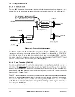
Generates periodic interrupts for use with a real-time operating system or the application software. The
periodic interrupt timer (PIT) is clocked by the timersclk clock, providing a period from 122 µs to
8 seconds. The PIT function can be disabled if needed. See Section 4.1.4, ÒPeriodic Interrupt Timer
(PIT).Ó
Time
counter
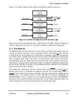
Provides a time-of-day information to the operating system/application software. It is composed of a
45-bit counter and an alarm register. A maskable interrupt is generated when the counter reaches the
value programmed in the alarm register. The time counter (TMCNT) is clocked by the timersclk clock.
See Section 4.1.3, ÒTime Counter (TMCNT).Ó
Summary of Contents for MPC8260 PowerQUICC II
Page 1: ...MPC8260UM D 4 1999 Rev 0 MPC8260 PowerQUICC II UserÕs Manual ª ª ...
Page 66: ...lxvi MPC8260 PowerQUICC II UserÕs Manual MOTOROLA ...
Page 88: ...1 18 MPC8260 PowerQUICC II UserÕs Manual MOTOROLA Part I Overview ...
Page 120: ...2 32 MPC8260 PowerQUICC II UserÕs Manual MOTOROLA Part I Overview ...
Page 138: ...Part II iv MPC8260 PowerQUICC II UserÕs Manual MOTOROLA Part II Configuration and Reset ...
Page 184: ...4 46 MPC8260 PowerQUICC II UserÕs Manual MOTOROLA Part II ConÞguration and Reset ...
Page 202: ...Part III vi MPC8260 PowerQUICC II UserÕs Manual MOTOROLA Part III The Hardware Interface ...
Page 266: ...8 34 MPC8260 PowerQUICC II UserÕs Manual MOTOROLA Part III The Hardware Interface ...
Page 382: ...10 106 MPC8260 PowerQUICC II UserÕs Manual MOTOROLA Part III The Hardware Interface ...
Page 392: ...11 10 MPC8260 PowerQUICC II UserÕs Manual MOTOROLA Part III The Hardware Interface ...
Page 430: ...Part IV viii MOTOROLA Part IV Communications Processor Module ...
Page 490: ...14 36 MPC8260 PowerQUICC II UserÕs Manual MOTOROLA Part IV Communications Processor Module ...
Page 524: ...17 10 MPC8260 PowerQUICC II UserÕs Manual MOTOROLA Part IV Communications Processor Module ...
Page 556: ...18 32 MPC8260 PowerQUICC II UserÕs Manual MOTOROLA Part IV Communications Processor Module ...
Page 584: ...19 28 MPC8260 PowerQUICC II UserÕs Manual MOTOROLA Part IV Communications Processor Module ...
Page 632: ...21 24 MPC8260 PowerQUICC II UserÕs Manual MOTOROLA Part IV Communications Processor Module ...
Page 652: ...22 20 MPC8260 PowerQUICC II UserÕs Manual MOTOROLA Part IV Communications Processor Module ...
Page 668: ...23 16 MPC8260 PowerQUICC II UserÕs Manual MOTOROLA Part IV Communications Processor Module ...
Page 758: ...27 28 MPC8260 PowerQUICC II UserÕs Manual MOTOROLA Part IV Communications Processor Module ...
Page 780: ...28 22 MPC8260 PowerQUICC II UserÕs Manual MOTOROLA Part IV Communications Processor Module ...
Page 874: ...29 94 MPC8260 PowerQUICC II UserÕs Manual MOTOROLA Part IV Communications Processor Module ...
Page 920: ...31 18 MPC8260 PowerQUICC II UserÕs Manual MOTOROLA Part IV Communications Processor Module ...
Page 980: ...A 4 MPC8260 PowerQUICC II UserÕs Manual MOTOROLA Appendixes ...
Page 1002: ...Index 22 MPC8260 PowerQUICC II UserÕs Manual MOTOROLA INDEX ...
Page 1006: ......

