


MOTOROLA
Chapter 10. Memory Controller
10-53
Part III. The Hardware Interface
10.5.1.1 Chip-Select Assertion Timing
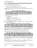
From 0 to 30 wait states can be programmed for PSDVAL generation. Byte-write enable
signals (WE) are available for each byte written to memory. Also, the output enable signal
(OE) is provided to eliminate external glue logic. The memory banks selected to work with
the GPCM have unique features. On system reset, a global (boot) chip-select is available
that provides a boot ROM chip-select prior to the system being fully conÞgured. The banks
selected to work with the GPCM support an option to output the CS line at different timings
with respect to the external address bus. CS can be output in any of three conÞgurations:
¥
Simultaneous with the external address
¥
One quarter of a clock cycle later
¥
One half of a clock cycle later
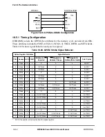
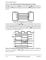
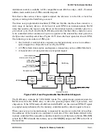
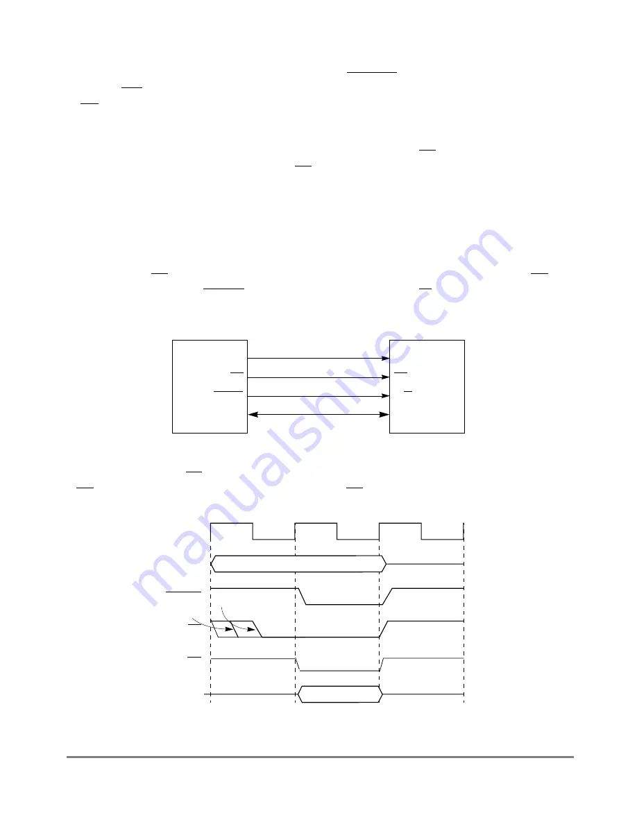
Figure 10-41 shows a basic connection between the MPC8260 and an external peripheral
device. Here, CS (the strobe output for the memory access) is connected directly to CE of
the memory device and BCTL0 is connected to the respective R/W in the peripheral device.
Figure 10-41. GPCM Peripheral Device Interface
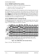
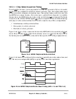
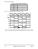
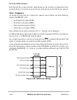
Figure 10-42 shows CS as deÞned by the setup time required between the address lines and
CE. The user can conÞgure OR
x
[ACS
]
to specify CS to meet this requirement.
Figure 10-42. GPCM Peripheral Device Basic Timing (ACS = 1x and TRLX = 0)
Address
CE
R/W
Data
Peripheral
Data
BCTL0
CS
Address
MPC8260
Clock
Address
PSDVAL
CS
OE
Data
ACS = 11
ACS = 10
Summary of Contents for MPC8260 PowerQUICC II
Page 1: ...MPC8260UM D 4 1999 Rev 0 MPC8260 PowerQUICC II UserÕs Manual ª ª ...
Page 66: ...lxvi MPC8260 PowerQUICC II UserÕs Manual MOTOROLA ...
Page 88: ...1 18 MPC8260 PowerQUICC II UserÕs Manual MOTOROLA Part I Overview ...
Page 120: ...2 32 MPC8260 PowerQUICC II UserÕs Manual MOTOROLA Part I Overview ...
Page 138: ...Part II iv MPC8260 PowerQUICC II UserÕs Manual MOTOROLA Part II Configuration and Reset ...
Page 184: ...4 46 MPC8260 PowerQUICC II UserÕs Manual MOTOROLA Part II ConÞguration and Reset ...
Page 202: ...Part III vi MPC8260 PowerQUICC II UserÕs Manual MOTOROLA Part III The Hardware Interface ...
Page 266: ...8 34 MPC8260 PowerQUICC II UserÕs Manual MOTOROLA Part III The Hardware Interface ...
Page 382: ...10 106 MPC8260 PowerQUICC II UserÕs Manual MOTOROLA Part III The Hardware Interface ...
Page 392: ...11 10 MPC8260 PowerQUICC II UserÕs Manual MOTOROLA Part III The Hardware Interface ...
Page 430: ...Part IV viii MOTOROLA Part IV Communications Processor Module ...
Page 490: ...14 36 MPC8260 PowerQUICC II UserÕs Manual MOTOROLA Part IV Communications Processor Module ...
Page 524: ...17 10 MPC8260 PowerQUICC II UserÕs Manual MOTOROLA Part IV Communications Processor Module ...
Page 556: ...18 32 MPC8260 PowerQUICC II UserÕs Manual MOTOROLA Part IV Communications Processor Module ...
Page 584: ...19 28 MPC8260 PowerQUICC II UserÕs Manual MOTOROLA Part IV Communications Processor Module ...
Page 632: ...21 24 MPC8260 PowerQUICC II UserÕs Manual MOTOROLA Part IV Communications Processor Module ...
Page 652: ...22 20 MPC8260 PowerQUICC II UserÕs Manual MOTOROLA Part IV Communications Processor Module ...
Page 668: ...23 16 MPC8260 PowerQUICC II UserÕs Manual MOTOROLA Part IV Communications Processor Module ...
Page 758: ...27 28 MPC8260 PowerQUICC II UserÕs Manual MOTOROLA Part IV Communications Processor Module ...
Page 780: ...28 22 MPC8260 PowerQUICC II UserÕs Manual MOTOROLA Part IV Communications Processor Module ...
Page 874: ...29 94 MPC8260 PowerQUICC II UserÕs Manual MOTOROLA Part IV Communications Processor Module ...
Page 920: ...31 18 MPC8260 PowerQUICC II UserÕs Manual MOTOROLA Part IV Communications Processor Module ...
Page 980: ...A 4 MPC8260 PowerQUICC II UserÕs Manual MOTOROLA Appendixes ...
Page 1002: ...Index 22 MPC8260 PowerQUICC II UserÕs Manual MOTOROLA INDEX ...
Page 1006: ......


