


MOTOROLA
Chapter 13. Communications Processor Module Overview
13-21
Part IV. Communications Processor Module
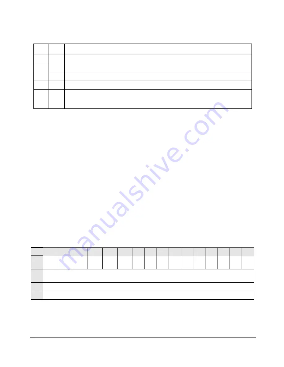
TM_CMD Þelds are described in Figure 13-11.
13.6.3 RISC Timer Table Entries
The 16 timers are located in the block of memory following the TM_BASE location; each
timer occupies 4 bytes. The Þrst half-word forms the initial value of the timer written during
the execution of the
SET
TIMER
command and the next half-word is the current value of the
timer that is decremented until it reaches zero. These locations should not be modiÞed by
the user. They are documented only as a debugging aid for user code. Use the
SET
TIMER
command to initialize table values.
13.6.4 RISC Timer Event Register (RTER)/Mask Register (RTMR)
The RTER is used to report events recognized by the 16 timers and to generate interrupts.
RTER can be read at any time. Bits are cleared by writing ones; writing zeros does not affect
bit values.
The RISC timer mask register (RTMR) is used to enable interrupts that can be generated in
the RTER. Setting an RTMR bit enables the corresponding interrupt in the RTER; clearing
a bit masks the corresponding interrupt. An interrupt is generated only if the RISC timer
table bit is set in the SIU interrupt mask register; see Section 4.3.1.5, ÒSIU Interrupt Mask
Registers (SIMR_H and SIMR_L).Ó
Figure 13-11. TM_CMD Field Descriptions
Bits
Name
Description
0
V
Valid. This bit should be set to enable the timer and cleared to disable it.
1
R
Restart. Should be set for an automatic restart or cleared for a one-shot operation of the timer.
2Ð11
Ñ
Reserved. These bits should be written with zeros.
12Ð15
TN
Timer number. A value from 0Ð15 signifying which timer to useÑan offset into the timer table entries.
16Ð31
TP
Timer period. The 16-bit timeout value of the timer is zero-based. The minimum value is 1 and is
programmed by writing 0x0000 to the timer period.The maximum value of the timer is 65,536 and is
programmed by writing 0xFFFF.
Bits
0
1
2
3
4
5
6
7
8
9
10
11
12
13
14
15
Field TMR1
5
TMR1
4
TMR1
3
TMR1
2
TMR1
1
TMR1
0
TMR
9
TMR
8
TMR
7
TMR
6
TMR
5
TMR
4
TMR
3
TMR
2
TMR
1
TMR
0
Res
et
0000_0000_0000_0000
R/W
R/W
Addr
0x119D6 (RTER)/0x119DA (RTMR)
Figure 13-12. RISC Timer Event Register (RTER)/Mask Register (RTMR)
Summary of Contents for MPC8260 PowerQUICC II
Page 1: ...MPC8260UM D 4 1999 Rev 0 MPC8260 PowerQUICC II UserÕs Manual ª ª ...
Page 66: ...lxvi MPC8260 PowerQUICC II UserÕs Manual MOTOROLA ...
Page 88: ...1 18 MPC8260 PowerQUICC II UserÕs Manual MOTOROLA Part I Overview ...
Page 120: ...2 32 MPC8260 PowerQUICC II UserÕs Manual MOTOROLA Part I Overview ...
Page 138: ...Part II iv MPC8260 PowerQUICC II UserÕs Manual MOTOROLA Part II Configuration and Reset ...
Page 184: ...4 46 MPC8260 PowerQUICC II UserÕs Manual MOTOROLA Part II ConÞguration and Reset ...
Page 202: ...Part III vi MPC8260 PowerQUICC II UserÕs Manual MOTOROLA Part III The Hardware Interface ...
Page 266: ...8 34 MPC8260 PowerQUICC II UserÕs Manual MOTOROLA Part III The Hardware Interface ...
Page 382: ...10 106 MPC8260 PowerQUICC II UserÕs Manual MOTOROLA Part III The Hardware Interface ...
Page 392: ...11 10 MPC8260 PowerQUICC II UserÕs Manual MOTOROLA Part III The Hardware Interface ...
Page 430: ...Part IV viii MOTOROLA Part IV Communications Processor Module ...
Page 490: ...14 36 MPC8260 PowerQUICC II UserÕs Manual MOTOROLA Part IV Communications Processor Module ...
Page 524: ...17 10 MPC8260 PowerQUICC II UserÕs Manual MOTOROLA Part IV Communications Processor Module ...
Page 556: ...18 32 MPC8260 PowerQUICC II UserÕs Manual MOTOROLA Part IV Communications Processor Module ...
Page 584: ...19 28 MPC8260 PowerQUICC II UserÕs Manual MOTOROLA Part IV Communications Processor Module ...
Page 632: ...21 24 MPC8260 PowerQUICC II UserÕs Manual MOTOROLA Part IV Communications Processor Module ...
Page 652: ...22 20 MPC8260 PowerQUICC II UserÕs Manual MOTOROLA Part IV Communications Processor Module ...
Page 668: ...23 16 MPC8260 PowerQUICC II UserÕs Manual MOTOROLA Part IV Communications Processor Module ...
Page 758: ...27 28 MPC8260 PowerQUICC II UserÕs Manual MOTOROLA Part IV Communications Processor Module ...
Page 780: ...28 22 MPC8260 PowerQUICC II UserÕs Manual MOTOROLA Part IV Communications Processor Module ...
Page 874: ...29 94 MPC8260 PowerQUICC II UserÕs Manual MOTOROLA Part IV Communications Processor Module ...
Page 920: ...31 18 MPC8260 PowerQUICC II UserÕs Manual MOTOROLA Part IV Communications Processor Module ...
Page 980: ...A 4 MPC8260 PowerQUICC II UserÕs Manual MOTOROLA Appendixes ...
Page 1002: ...Index 22 MPC8260 PowerQUICC II UserÕs Manual MOTOROLA INDEX ...
Page 1006: ......


