17-2
MPC8260 PowerQUICC II UserÕs Manual
MOTOROLA
Part IV. Communications Processor Module
17.1 Features
The key features of the timer include the following:
¥
The maximum input clock is the bus clock
¥
Maximum period of 4 seconds (at 66 MHz)
¥
16-nanosecond resolution (at 66 MHz)
¥
Programmable sources for the clock input
¥
Input capture capability
¥
Output compare with programmable mode for the output pin
¥
Two timers cascade internally or externally to form a 32-bit timer
¥
Free run and restart modes
¥
Functional compatibility with timers on the MC68360 and MPC860
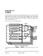
17.2 General-Purpose Timer Units
The clock input to the prescaler can be selected from three sources:
¥
The bus clock (CLKIN)
¥
The bus clock divided by 16 (CLKIN/16)
¥
The corresponding TIN
x
, programmed in the parallel port registers
The general system clock is generated in the clock synthesizer and defaults to the system
frequency. However, the general system clock has the option to be divided before it leaves
the clock synthesizer. This mode, called slow go, is used to save power. Whatever the
resulting frequency of the general system clock, the user can either choose that frequency
or the frequency divided by 16 as the input to the prescaler of each timer. Alternatively, the
user may prefer TIN
x
to be the clock source. TIN
x
is internally synchronized to the internal
clock. If the user has chosen to internally cascade two 16-bit timers to a 32-bit timer, then
a timer can use the clock generated by the output of another timer.
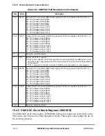
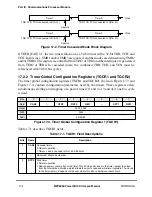
The clock input source is selected by the corresponding TMR[ICLK] bits. The prescaler is
programmed to divide the clock input by values from 1 to 256 and the output of the
prescaler is used as an input to the 16-bit counter. The best resolution of the timer is one
clock cycle (16 ns at 66 MHz). The maximum period (when the reference value is all ones)
is 268,435,456 cycles (4 seconds at 66 MHz).
Each timer can be conÞgured to count until a reference is reached and then either begin a
new time count immediately or continue to run. The FRR bit of the corresponding TMR
selects each mode. Upon reaching the reference value, the corresponding TER bit is set and
an interrupt is issued if TMR[ORI] = 1. The timers can output a signal on the timer outputs
(TOUT1ÐTOUT4) when the reference value is reached (selected by the corresponding
TMR[OM]). This signal can be an active-low pulse or a toggle of the current output. The
Summary of Contents for MPC8260 PowerQUICC II
Page 1: ...MPC8260UM D 4 1999 Rev 0 MPC8260 PowerQUICC II UserÕs Manual ª ª ...
Page 66: ...lxvi MPC8260 PowerQUICC II UserÕs Manual MOTOROLA ...
Page 88: ...1 18 MPC8260 PowerQUICC II UserÕs Manual MOTOROLA Part I Overview ...
Page 120: ...2 32 MPC8260 PowerQUICC II UserÕs Manual MOTOROLA Part I Overview ...
Page 138: ...Part II iv MPC8260 PowerQUICC II UserÕs Manual MOTOROLA Part II Configuration and Reset ...
Page 184: ...4 46 MPC8260 PowerQUICC II UserÕs Manual MOTOROLA Part II ConÞguration and Reset ...
Page 202: ...Part III vi MPC8260 PowerQUICC II UserÕs Manual MOTOROLA Part III The Hardware Interface ...
Page 266: ...8 34 MPC8260 PowerQUICC II UserÕs Manual MOTOROLA Part III The Hardware Interface ...
Page 382: ...10 106 MPC8260 PowerQUICC II UserÕs Manual MOTOROLA Part III The Hardware Interface ...
Page 392: ...11 10 MPC8260 PowerQUICC II UserÕs Manual MOTOROLA Part III The Hardware Interface ...
Page 430: ...Part IV viii MOTOROLA Part IV Communications Processor Module ...
Page 490: ...14 36 MPC8260 PowerQUICC II UserÕs Manual MOTOROLA Part IV Communications Processor Module ...
Page 524: ...17 10 MPC8260 PowerQUICC II UserÕs Manual MOTOROLA Part IV Communications Processor Module ...
Page 556: ...18 32 MPC8260 PowerQUICC II UserÕs Manual MOTOROLA Part IV Communications Processor Module ...
Page 584: ...19 28 MPC8260 PowerQUICC II UserÕs Manual MOTOROLA Part IV Communications Processor Module ...
Page 632: ...21 24 MPC8260 PowerQUICC II UserÕs Manual MOTOROLA Part IV Communications Processor Module ...
Page 652: ...22 20 MPC8260 PowerQUICC II UserÕs Manual MOTOROLA Part IV Communications Processor Module ...
Page 668: ...23 16 MPC8260 PowerQUICC II UserÕs Manual MOTOROLA Part IV Communications Processor Module ...
Page 758: ...27 28 MPC8260 PowerQUICC II UserÕs Manual MOTOROLA Part IV Communications Processor Module ...
Page 780: ...28 22 MPC8260 PowerQUICC II UserÕs Manual MOTOROLA Part IV Communications Processor Module ...
Page 874: ...29 94 MPC8260 PowerQUICC II UserÕs Manual MOTOROLA Part IV Communications Processor Module ...
Page 920: ...31 18 MPC8260 PowerQUICC II UserÕs Manual MOTOROLA Part IV Communications Processor Module ...
Page 980: ...A 4 MPC8260 PowerQUICC II UserÕs Manual MOTOROLA Appendixes ...
Page 1002: ...Index 22 MPC8260 PowerQUICC II UserÕs Manual MOTOROLA INDEX ...
Page 1006: ......

