18-16
MPC8260 PowerQUICC II UserÕs Manual
MOTOROLA
Part IV. Communications Processor Module
18.8.2 IDMA
x
Parameter RAM
When an IDMA
x
channel is conÞgured to auto buffer or buffer chaining mode, the
MPC8260 uses the IDMA
x
parameters listed in the Table 18-4. Parameters should be
modiÞed only while the channel is disabled, that is, before the Þrst
START
_
IDMA
command
or when the event registerÕs stop-completed bit (IDSR[SC]) is set following a
STOP
_
IDMA
command.
Each IDMA
x
channel parameter table can be placed at any 64-byte aligned address in the
dual-port RAMÕs general-purpose area (banks 1Ð8). The CP accesses each IDMA
x
channel
parameter table using a user-programmed pointer (IDMA
x
_BASE) located in the
parameter RAM; see Section 13.5.2, ÒParameter RAM.Ó For example, if the IDMA1
channel parameter table is to be placed at address offset 0x2000 in the dual-port RAM,
write 0x2000 to IDMA1_BASE.
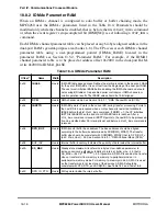
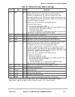
Table 18-4. IDMA
x
Parameter RAM
Offset
1
Name
Width
Description
0x00
IBASE
Hword IDMA BD table base address. DeÞnes the starting location in the dual-port RAM
for the set of IDMA BDs. It is an offset from the beginning of the dual-port RAM.
The user must initialize IBASE before enabling the IDMA channel and should
not overlap BD tables of two enabled serial controllers or IDMA channels or
erratic operation results. The IBASE value should be 16-bit aligned.
0x02
DCM
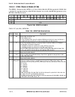
Hword DMA channel mode. See Section 18.8.2.1, ÒDMA Channel Mode (DCM).Ó
0x04
IBDPTR
Hword IDMA BD pointer. Points to the current BD during transfer processing. Points to
the next BD to be processed when an idle channel is restarted. Initialize to
IBASE before the Þrst
START
_
IDMA
command. If BD[W] = 1, the CP initializes
IBPTR to IBASE When the end of an IDMA BD table is reached. After a
STOP
_
IDMA
command is issued, IBDPTR points to the next BD to be processed.
It can be modiÞed after SC interrupt is set and before a
START
_
IDMA
command is
reissued.
0x06
DPR_BUF
Hword IDMA transfer buffer base address. The base address should be aligned
according to the buffer size determined by DCM[DMA_WRAP]. The transfer
buffer size should be consistent with DCM[DMA_WRAP]; that is, DPR_BUF =
(64 X 2
DMA_WRAP
) - 32. See Section 18.8.2.1, ÒDMA Channel Mode (DCM).Ó
0x08
BUF_INV
Hword Internal buffer inventory. Indicates the quantity of data inside the internal buffer.
0x0A
SS_MAX
Hword Steady-state maximum transfer size in bytes. User-deÞned parameter to
increase microcode efÞciency. Initialize to internal_buffer_size - 32, that is,
SS_MAX = (64 X 2
DMA_WRAP
) - 32. If possible, SS_MAX is used as the transfer
size on transfers to/from memory in memory-to-peripheral mode or in
peripheral-to-memory mode. For memory-to-memory mode, SS_MAX is used
as the transfer size for at least one of the devices. SS_MAX should be
consistent with STS, DTS, and DCM[S/D]. See Table 18-7 and Table 18-8.
0x0C
DPR_IN_PTR
Hword Write pointer inside the internal buffer.
Summary of Contents for MPC8260 PowerQUICC II
Page 1: ...MPC8260UM D 4 1999 Rev 0 MPC8260 PowerQUICC II UserÕs Manual ª ª ...
Page 66: ...lxvi MPC8260 PowerQUICC II UserÕs Manual MOTOROLA ...
Page 88: ...1 18 MPC8260 PowerQUICC II UserÕs Manual MOTOROLA Part I Overview ...
Page 120: ...2 32 MPC8260 PowerQUICC II UserÕs Manual MOTOROLA Part I Overview ...
Page 138: ...Part II iv MPC8260 PowerQUICC II UserÕs Manual MOTOROLA Part II Configuration and Reset ...
Page 184: ...4 46 MPC8260 PowerQUICC II UserÕs Manual MOTOROLA Part II ConÞguration and Reset ...
Page 202: ...Part III vi MPC8260 PowerQUICC II UserÕs Manual MOTOROLA Part III The Hardware Interface ...
Page 266: ...8 34 MPC8260 PowerQUICC II UserÕs Manual MOTOROLA Part III The Hardware Interface ...
Page 382: ...10 106 MPC8260 PowerQUICC II UserÕs Manual MOTOROLA Part III The Hardware Interface ...
Page 392: ...11 10 MPC8260 PowerQUICC II UserÕs Manual MOTOROLA Part III The Hardware Interface ...
Page 430: ...Part IV viii MOTOROLA Part IV Communications Processor Module ...
Page 490: ...14 36 MPC8260 PowerQUICC II UserÕs Manual MOTOROLA Part IV Communications Processor Module ...
Page 524: ...17 10 MPC8260 PowerQUICC II UserÕs Manual MOTOROLA Part IV Communications Processor Module ...
Page 556: ...18 32 MPC8260 PowerQUICC II UserÕs Manual MOTOROLA Part IV Communications Processor Module ...
Page 584: ...19 28 MPC8260 PowerQUICC II UserÕs Manual MOTOROLA Part IV Communications Processor Module ...
Page 632: ...21 24 MPC8260 PowerQUICC II UserÕs Manual MOTOROLA Part IV Communications Processor Module ...
Page 652: ...22 20 MPC8260 PowerQUICC II UserÕs Manual MOTOROLA Part IV Communications Processor Module ...
Page 668: ...23 16 MPC8260 PowerQUICC II UserÕs Manual MOTOROLA Part IV Communications Processor Module ...
Page 758: ...27 28 MPC8260 PowerQUICC II UserÕs Manual MOTOROLA Part IV Communications Processor Module ...
Page 780: ...28 22 MPC8260 PowerQUICC II UserÕs Manual MOTOROLA Part IV Communications Processor Module ...
Page 874: ...29 94 MPC8260 PowerQUICC II UserÕs Manual MOTOROLA Part IV Communications Processor Module ...
Page 920: ...31 18 MPC8260 PowerQUICC II UserÕs Manual MOTOROLA Part IV Communications Processor Module ...
Page 980: ...A 4 MPC8260 PowerQUICC II UserÕs Manual MOTOROLA Appendixes ...
Page 1002: ...Index 22 MPC8260 PowerQUICC II UserÕs Manual MOTOROLA INDEX ...
Page 1006: ......

