


18-24
MPC8260 PowerQUICC II UserÕs Manual
MOTOROLA
Part IV. Communications Processor Module
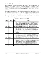
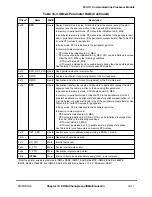
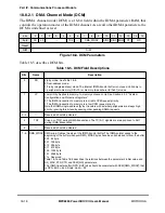
Table 18-10 describes IDMA BD Þelds.
Table 18-10. IDMA BD Field Descriptions
Offset
Bits
Name
Description
0x00
0
V
Valid
0 This BD does not contain valid data for transfer.
1 This BD contain valid data for transfer.
The CP checks this bit before starting a BD service. If this bit is cleared when the CP
accesses the BD, an interrupt IDSR[OB] is issued to the core, the IDMA channel is
stopped until a
START
_
IDMA
command is issued. After the BD is serviced this bit is
cleared by CP unless CM = 1.
1
Ñ
Reserved, should be cleared.
2
W
Wrap (Þnal BD in table)
0 This is not the last BD in the BD table.
1 Last BD in the table. After the associated buffer has been used, the CP transfers data
from the Þrst BD in the table, which is pointed by IBASE. The number of BDs in this
table is programmable and determined by W bit and the overall space constraints of the
dual-port RAM.
3
I
Interrupt
0 No interrupt is generated after this buffer is serviced.
1 When the CP services all the bufferÕs data, IDSR[BC] is set, which generates a
maskable interrupt.
4
L
Last
0 Not the last buffer of a chain to be transferred in buffer chaining mode. The I bit can be
used to generate an interrupt when this buffer service is complete.
1 Last buffer of a chain to be transferred in buffer chaining mode. When this BD service is
complete the channel is stopped by CP until
START
_
IDMA
command is issued.
This bit should be set only in buffer chaining mode (CM bit 6 = 0).
5
Ñ
Reserved, should be cleared.
6
CM
Continuous mode
0 Buffer chaining mode. The CP clears V after this BD is serviced. Buffer chaining mode
is used to transfer large quantities of data into non-contiguous buffer areas. The user
can initialize BDs ahead of time, if needed. The CP automatically loads the IDMA
registers from the next BD values when the transfer is terminated.
1 Auto buffer mode (continuous mode). The CP does not clear V after this BD is serviced.
This is the only difference between auto buffer mode and buffer chaining mode. Auto
buffer mode transfers multiple groups of data to/from a buffer table and does not
require BD reprogramming. The CP automatically reloads the IDMA registers from the
next BD values when the transfer is terminated. Either a single BD or multiple BDs can
be used to create an inÞnite loop of repeated data moves.
Note that the I bit can still be used to generate an interrupt in this mode.
7-8
Ñ
Reserved, should be cleared.
9
SDN
Source done
0 DONE is inactive during this BD.
1 The IDMA asserts DONE at the last read data phase of the BD.
In ßy-by mode (DCM[FB] = 1), SDN should be same as DDN.
10
DDN
Destination done
0 DONE is inactive during this BD.
1 The IDMA asserts DONE at the last write data phase of the BD.
In ßy-by mode (DCM[FB] = 1), DDN should be same as SDN.
Summary of Contents for MPC8260 PowerQUICC II
Page 1: ...MPC8260UM D 4 1999 Rev 0 MPC8260 PowerQUICC II UserÕs Manual ª ª ...
Page 66: ...lxvi MPC8260 PowerQUICC II UserÕs Manual MOTOROLA ...
Page 88: ...1 18 MPC8260 PowerQUICC II UserÕs Manual MOTOROLA Part I Overview ...
Page 120: ...2 32 MPC8260 PowerQUICC II UserÕs Manual MOTOROLA Part I Overview ...
Page 138: ...Part II iv MPC8260 PowerQUICC II UserÕs Manual MOTOROLA Part II Configuration and Reset ...
Page 184: ...4 46 MPC8260 PowerQUICC II UserÕs Manual MOTOROLA Part II ConÞguration and Reset ...
Page 202: ...Part III vi MPC8260 PowerQUICC II UserÕs Manual MOTOROLA Part III The Hardware Interface ...
Page 266: ...8 34 MPC8260 PowerQUICC II UserÕs Manual MOTOROLA Part III The Hardware Interface ...
Page 382: ...10 106 MPC8260 PowerQUICC II UserÕs Manual MOTOROLA Part III The Hardware Interface ...
Page 392: ...11 10 MPC8260 PowerQUICC II UserÕs Manual MOTOROLA Part III The Hardware Interface ...
Page 430: ...Part IV viii MOTOROLA Part IV Communications Processor Module ...
Page 490: ...14 36 MPC8260 PowerQUICC II UserÕs Manual MOTOROLA Part IV Communications Processor Module ...
Page 524: ...17 10 MPC8260 PowerQUICC II UserÕs Manual MOTOROLA Part IV Communications Processor Module ...
Page 556: ...18 32 MPC8260 PowerQUICC II UserÕs Manual MOTOROLA Part IV Communications Processor Module ...
Page 584: ...19 28 MPC8260 PowerQUICC II UserÕs Manual MOTOROLA Part IV Communications Processor Module ...
Page 632: ...21 24 MPC8260 PowerQUICC II UserÕs Manual MOTOROLA Part IV Communications Processor Module ...
Page 652: ...22 20 MPC8260 PowerQUICC II UserÕs Manual MOTOROLA Part IV Communications Processor Module ...
Page 668: ...23 16 MPC8260 PowerQUICC II UserÕs Manual MOTOROLA Part IV Communications Processor Module ...
Page 758: ...27 28 MPC8260 PowerQUICC II UserÕs Manual MOTOROLA Part IV Communications Processor Module ...
Page 780: ...28 22 MPC8260 PowerQUICC II UserÕs Manual MOTOROLA Part IV Communications Processor Module ...
Page 874: ...29 94 MPC8260 PowerQUICC II UserÕs Manual MOTOROLA Part IV Communications Processor Module ...
Page 920: ...31 18 MPC8260 PowerQUICC II UserÕs Manual MOTOROLA Part IV Communications Processor Module ...
Page 980: ...A 4 MPC8260 PowerQUICC II UserÕs Manual MOTOROLA Appendixes ...
Page 1002: ...Index 22 MPC8260 PowerQUICC II UserÕs Manual MOTOROLA INDEX ...
Page 1006: ......


