


MOTOROLA
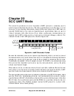
Chapter 20. SCC UART Mode
20-15
Part IV. Communications Processor Module
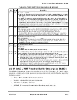
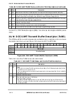
20.17 SCC UART Receive Buffer Descriptor (RxBD)
The CPM uses RxBDs to report on each buffer received. The CPM closes the current buffer,
generates a maskable interrupt, and starts receiving data into the next buffer after one of the
following occurs:
¥
A user-deÞned control character is received.
¥
An error occurs during message processing.
¥
A full receive buffer is detected.
¥
A MAX_IDL number of consecutive idle characters is received.
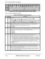
7
RZS
Receive zero stop bits.
0 The receiver operates normally, but at least one stop bit is needed between characters. A framing
error is issued if a stop bit is missing. Break status is set if an all-zero character is received with a
zero stop bit.
1 ConÞgures the receiver to receive data without stop bits. Useful in V.14 applications where SCC
UART controller data is supplied synchronously and all stop bits of a particular character can be
omitted for cross-network rate adaptation. RZS should be set only if SYN is set. The receiver
continues if a stop bit is missing. If the stop bit is a zero, the next bit is considered the Þrst data bit
of the next character. A framing error is issued if a stop bit is missing, but a break status is reported
only after two consecutive break characters have no stop bits.
8
SYN
Synchronous mode.
0 Normal asynchronous operation. GSMR_L[TENC,RENC] must select NRZ and GSMR_L[TDCR,
RDCR] select either 8
´
, 16
´
, or 32
´
. 16
´
is recommended for most applications.
1 Synchronous SCC UART controller using 1
´
clock (isochronous UART operation).
GSMR_L[TENC, RENC] must select NRZ and GSMR_L[RDCR, TDCR] select 1
´
mode. A bit is
transferred with each clock and is synchronous to the clock, which can be internal or external.
9
DRT
Disable receiver while transmitting.
0 Normal operation.
1 While the SCC is sending data, the internal RTS disables and gates the receiver. Useful for a
multidrop conÞguration in which the user does not want to receive its own transmission. For
multidrop UART mode, set the BDsÕ preamble bit, TxBD[P].
10
Ñ
Reserved, should be cleared.
11
PEN
Parity enable.
0 No parity.
1 Parity is enabled and determined by the parity mode bits.
12Ð13,
14Ð15
RPM,
TPM
Receiver/transmitter parity mode. Selects the type of parity check the receiver/transmitter performs;
can be modiÞed on-the-ßy. Receive parity errors can be ignored but not disabled.
00 Odd parity. If a transmitter counts an even number of ones in the data word, it sets the parity bit
so an odd number is sent. If a receiver receives an even number, a parity error is reported.
01 Low parity (space parity). A transmitter sends a zero in the parity bit position. If a receiver does
not read a 0 in the parity bit, a parity error is reported.
10 Even parity. Like odd parity, the transmitter adjusts the parity bit, as necessary, to ensure that the
receiver receives an even number of one bits; otherwise, a parity error is reported.
11 High parity (mark parity). The transmitter sends a one in the parity bit position. If the receiver
does not read a 1 in the parity bit, a parity error is reported.
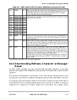
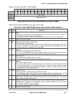
Table 20-9. PSMR UART Field Descriptions (Continued)
Bit
Name
Description
Summary of Contents for MPC8260 PowerQUICC II
Page 1: ...MPC8260UM D 4 1999 Rev 0 MPC8260 PowerQUICC II UserÕs Manual ª ª ...
Page 66: ...lxvi MPC8260 PowerQUICC II UserÕs Manual MOTOROLA ...
Page 88: ...1 18 MPC8260 PowerQUICC II UserÕs Manual MOTOROLA Part I Overview ...
Page 120: ...2 32 MPC8260 PowerQUICC II UserÕs Manual MOTOROLA Part I Overview ...
Page 138: ...Part II iv MPC8260 PowerQUICC II UserÕs Manual MOTOROLA Part II Configuration and Reset ...
Page 184: ...4 46 MPC8260 PowerQUICC II UserÕs Manual MOTOROLA Part II ConÞguration and Reset ...
Page 202: ...Part III vi MPC8260 PowerQUICC II UserÕs Manual MOTOROLA Part III The Hardware Interface ...
Page 266: ...8 34 MPC8260 PowerQUICC II UserÕs Manual MOTOROLA Part III The Hardware Interface ...
Page 382: ...10 106 MPC8260 PowerQUICC II UserÕs Manual MOTOROLA Part III The Hardware Interface ...
Page 392: ...11 10 MPC8260 PowerQUICC II UserÕs Manual MOTOROLA Part III The Hardware Interface ...
Page 430: ...Part IV viii MOTOROLA Part IV Communications Processor Module ...
Page 490: ...14 36 MPC8260 PowerQUICC II UserÕs Manual MOTOROLA Part IV Communications Processor Module ...
Page 524: ...17 10 MPC8260 PowerQUICC II UserÕs Manual MOTOROLA Part IV Communications Processor Module ...
Page 556: ...18 32 MPC8260 PowerQUICC II UserÕs Manual MOTOROLA Part IV Communications Processor Module ...
Page 584: ...19 28 MPC8260 PowerQUICC II UserÕs Manual MOTOROLA Part IV Communications Processor Module ...
Page 632: ...21 24 MPC8260 PowerQUICC II UserÕs Manual MOTOROLA Part IV Communications Processor Module ...
Page 652: ...22 20 MPC8260 PowerQUICC II UserÕs Manual MOTOROLA Part IV Communications Processor Module ...
Page 668: ...23 16 MPC8260 PowerQUICC II UserÕs Manual MOTOROLA Part IV Communications Processor Module ...
Page 758: ...27 28 MPC8260 PowerQUICC II UserÕs Manual MOTOROLA Part IV Communications Processor Module ...
Page 780: ...28 22 MPC8260 PowerQUICC II UserÕs Manual MOTOROLA Part IV Communications Processor Module ...
Page 874: ...29 94 MPC8260 PowerQUICC II UserÕs Manual MOTOROLA Part IV Communications Processor Module ...
Page 920: ...31 18 MPC8260 PowerQUICC II UserÕs Manual MOTOROLA Part IV Communications Processor Module ...
Page 980: ...A 4 MPC8260 PowerQUICC II UserÕs Manual MOTOROLA Appendixes ...
Page 1002: ...Index 22 MPC8260 PowerQUICC II UserÕs Manual MOTOROLA INDEX ...
Page 1006: ......


