


26-4
MPC8260 PowerQUICC II UserÕs Manual
MOTOROLA
Part IV. Communications Processor Module
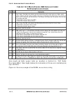
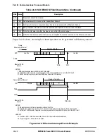
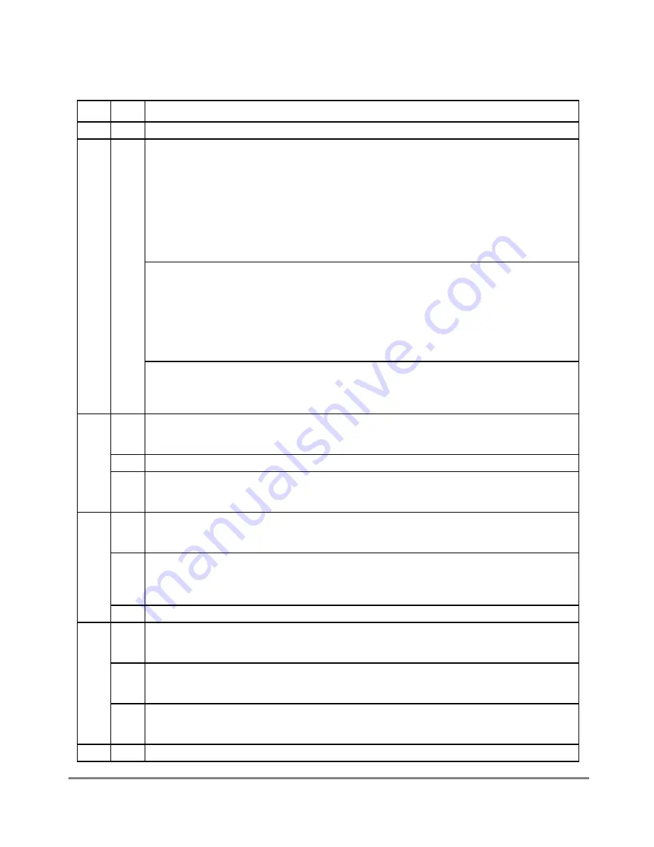
Table 26-1 describes SMCMR Þelds.
Table 26-1. SMCMR1/SMCMR2 Field Descriptions
Bits
Name
Description
0
Ñ
Reserved, should be cleared.
1Ð4
CLEN Character length (UART). Number of bits in the character minus one. The total is the sum of 1 (start
bit always present) + number of data bits (5Ð14) + number of parity bits (0 or 1) + number of stop bits
(1 or 2). For example, for 8 data bits, no parity, and 1 stop bit, the total number of bits in the character
is 1 + 8 + 0 + 1 = 10. So, CLEN should be programmed to 9.
Characters range from 5Ð14 bits. If the data bit length is less than 8, the msbs of each byte in
memory are not used on transmit and are written with zeros on receive. If the length is more than 8,
the msbs of each 16-bit word are not used on transmit and are written with zeros on receive.
The character must not exceed 16 bits. For a 14-bit data length, set SL to one stop bit and disable
parity. For a 13-bit data length with parity enabled, set SL to one stop bit. Writing values 0 to 3 to
CLEN causes erratic behavior.
Character length (transparent). The values 3Ð15 specify 4Ð16 bits per character. If a character is less
than 8 bits, the most-signiÞcant bits of the byte in buffer memory are not used on transmit and are
written with zeros on receive. If character length is more than 8 bits but less than 16, the most-
signiÞcant bits of the half-word in buffer memory are not used on transmit and are written with zeros
on receive.
Note: Using values 0Ð2 causes erratic behavior. Larger character lengths increase an SMC channelÕs
potential performance and lowers the performance impact of other channels. For instance, using 16-
rather than 8-bit characters is encouraged if 16-bit characters are acceptable in the end application.
Character length (GCI). Number of bits in the C/I and monitor channels of the SCIT channels 0 or 1.
(values 0Ð15 correspond to 1Ð16 bits) CLEN should be 13 for SCIT channel 0 or GCI (8 data bits,
plus A and E bits, plus 4 C/I bits = 14 bits). It should be 15 for the SCIT channel 1 (8 data, bits, plus A
and E bits, plus 6 C/I bits = 16 bits).
5
SL
Stop length. (UART)
0 One stop bit.
1 Two stop bits.
Ñ
Reserved, should be cleared. (transparent)
ME
Monitor enable. (GCI)
0 The SMC does not support the monitor channel.
1 The SMC supports the monitor channel.
6
PEN
Parity enable. (UART)
0 No parity.
1 Parity is enabled for the transmitter and receiver as determined by the PM bit.
BS
Byte sequence(transparent). Controls the byte transmission sequence if REVD is set for a character
length greater than 8 bits. Clear BS to maintain behavior compatibility with MC68360 QUICC.
0 Normal mode. This should be selected if the character length is not larger than 8 bits.
1 Transmit lower address byte Þrst.
Ñ
Reserved, should be cleared. (GCI)
7
PM
Parity mode. (UART)
0 Odd parity.
1 Even parity.
REVD Reverse data. (transparent)
0 Normal mode.
1 Reverse the character bit order. The msb is sent Þrst.
C#
SCIT channel number. (GCI)
0 SCIT channel 0
1 SCIT channel 1. Required for Siemens ARCOFI and SGS S/T chips.
8Ð9
Ñ
Reserved, should be cleared.
Summary of Contents for MPC8260 PowerQUICC II
Page 1: ...MPC8260UM D 4 1999 Rev 0 MPC8260 PowerQUICC II UserÕs Manual ª ª ...
Page 66: ...lxvi MPC8260 PowerQUICC II UserÕs Manual MOTOROLA ...
Page 88: ...1 18 MPC8260 PowerQUICC II UserÕs Manual MOTOROLA Part I Overview ...
Page 120: ...2 32 MPC8260 PowerQUICC II UserÕs Manual MOTOROLA Part I Overview ...
Page 138: ...Part II iv MPC8260 PowerQUICC II UserÕs Manual MOTOROLA Part II Configuration and Reset ...
Page 184: ...4 46 MPC8260 PowerQUICC II UserÕs Manual MOTOROLA Part II ConÞguration and Reset ...
Page 202: ...Part III vi MPC8260 PowerQUICC II UserÕs Manual MOTOROLA Part III The Hardware Interface ...
Page 266: ...8 34 MPC8260 PowerQUICC II UserÕs Manual MOTOROLA Part III The Hardware Interface ...
Page 382: ...10 106 MPC8260 PowerQUICC II UserÕs Manual MOTOROLA Part III The Hardware Interface ...
Page 392: ...11 10 MPC8260 PowerQUICC II UserÕs Manual MOTOROLA Part III The Hardware Interface ...
Page 430: ...Part IV viii MOTOROLA Part IV Communications Processor Module ...
Page 490: ...14 36 MPC8260 PowerQUICC II UserÕs Manual MOTOROLA Part IV Communications Processor Module ...
Page 524: ...17 10 MPC8260 PowerQUICC II UserÕs Manual MOTOROLA Part IV Communications Processor Module ...
Page 556: ...18 32 MPC8260 PowerQUICC II UserÕs Manual MOTOROLA Part IV Communications Processor Module ...
Page 584: ...19 28 MPC8260 PowerQUICC II UserÕs Manual MOTOROLA Part IV Communications Processor Module ...
Page 632: ...21 24 MPC8260 PowerQUICC II UserÕs Manual MOTOROLA Part IV Communications Processor Module ...
Page 652: ...22 20 MPC8260 PowerQUICC II UserÕs Manual MOTOROLA Part IV Communications Processor Module ...
Page 668: ...23 16 MPC8260 PowerQUICC II UserÕs Manual MOTOROLA Part IV Communications Processor Module ...
Page 758: ...27 28 MPC8260 PowerQUICC II UserÕs Manual MOTOROLA Part IV Communications Processor Module ...
Page 780: ...28 22 MPC8260 PowerQUICC II UserÕs Manual MOTOROLA Part IV Communications Processor Module ...
Page 874: ...29 94 MPC8260 PowerQUICC II UserÕs Manual MOTOROLA Part IV Communications Processor Module ...
Page 920: ...31 18 MPC8260 PowerQUICC II UserÕs Manual MOTOROLA Part IV Communications Processor Module ...
Page 980: ...A 4 MPC8260 PowerQUICC II UserÕs Manual MOTOROLA Appendixes ...
Page 1002: ...Index 22 MPC8260 PowerQUICC II UserÕs Manual MOTOROLA INDEX ...
Page 1006: ......


