27-22
MPC8260 PowerQUICC II UserÕs Manual
MOTOROLA
Part IV. Communications Processor Module
5
F
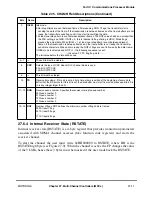
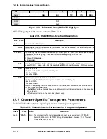
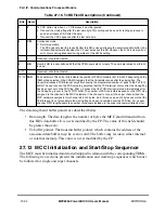
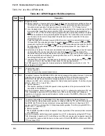
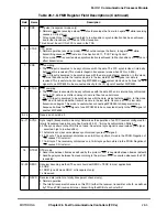
First in frame. The HDLC controller sets F = 1 for the Þrst buffer in a frame. In transparent mode, F
indicates that there was a synchronization before receiving data in this BD.
0 This is not the Þrst buffer in a frame.
1 This is the Þrst buffer in a frame.
6
CM
Continuous mode
0 Normal operation (The empty bit (bit 0) is cleared by the CP after this BD is closed).
1 The empty bit (bit 0) is not cleared by the CP after this BD is closed, allowing the associated data
buffer to be overwritten automatically when the CP next accesses this BD. However, if an error
occurs during reception, the empty bit is cleared regardless of the CM bit setting.
7
Ñ
Reserved, should be cleared.
8
UB
User bit. UB is a user-deÞned bit that the CPM never sets nor clears. The user determines how this
bit is used.
9
Ñ
Reserved, should be cleared.
10
LG
Rx frame length violation (HDLC mode only). Indicates that a frame length greater than the
maximum value was received in this channel. Only the maximum-allowed number of bytes, MFLR
rounded to the nearest higher word alignment, are written to the data buffer. This event is recognized
as soon as the MFLR value is exceeded when data is word-aligned. When data is not word-aligned,
this interrupt occurs when the SDMA writes 64 bits to memory. The worst-case latency from MFLR
violation until detected is 7 bytes timing for this channel. When MFLR violation is detected, the
receiver is still receiving even though the data is discarded. The buffer is closed upon detecting a
ßag, and this is considered to be the closing ßag for this buffer. At this point, LG is set (1) and an
interrupt may be generated. The length Þeld for this buffer is everything between the opening ßag
and this last identifying ßag.
11
NO
Rx nonoctet-aligned frame. A frame of bits not divisible exactly by eight was received. NO = 1 for any
type of nonalignment regardless of frame length. The shortest frame that can be detected is of type
FLAG-BIT-FLAG, which causes the buffer to be closed with NO error indicated.
The following shows how the nonoctet alignment is reported and where data can be found.
To accommodate the extra word of data that may be written at the end of the frame, it is
recommended to reserve MFLR + 8 bytes for each buffer data.
12
AB
Rx abort sequence. A minimum of seven consecutive 1s was received during frame reception. Abort
is not detected between frames. The sequence
Closing-Flag, data, CRC, AB, data, opening-ßag...
does not cause an abort error. If the abort is long enough to be an idle, an idle line interrupt may be
generated. An abort within the frame is not reported by a unique interrupt but rather with a RXF
interrupt and the user has to examine the BD.
13
CR
Rx CRC error. This frame contains a CRC error. The received CRC bytes are always written to the
receive buffer.
14Ð15 Ñ
Reserved, should be cleared.
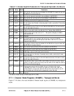
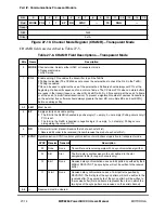
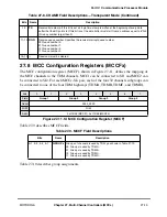
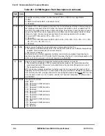
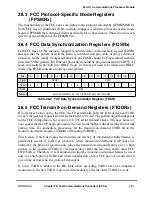
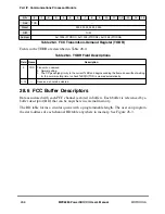
Table 27-15. RxBD Field Descriptions (Continued)
Bits
Name
Description
msb
lsb
1
000...... 0
Valid data
Invalid data
xxx .................................... xx
Summary of Contents for MPC8260 PowerQUICC II
Page 1: ...MPC8260UM D 4 1999 Rev 0 MPC8260 PowerQUICC II UserÕs Manual ª ª ...
Page 66: ...lxvi MPC8260 PowerQUICC II UserÕs Manual MOTOROLA ...
Page 88: ...1 18 MPC8260 PowerQUICC II UserÕs Manual MOTOROLA Part I Overview ...
Page 120: ...2 32 MPC8260 PowerQUICC II UserÕs Manual MOTOROLA Part I Overview ...
Page 138: ...Part II iv MPC8260 PowerQUICC II UserÕs Manual MOTOROLA Part II Configuration and Reset ...
Page 184: ...4 46 MPC8260 PowerQUICC II UserÕs Manual MOTOROLA Part II ConÞguration and Reset ...
Page 202: ...Part III vi MPC8260 PowerQUICC II UserÕs Manual MOTOROLA Part III The Hardware Interface ...
Page 266: ...8 34 MPC8260 PowerQUICC II UserÕs Manual MOTOROLA Part III The Hardware Interface ...
Page 382: ...10 106 MPC8260 PowerQUICC II UserÕs Manual MOTOROLA Part III The Hardware Interface ...
Page 392: ...11 10 MPC8260 PowerQUICC II UserÕs Manual MOTOROLA Part III The Hardware Interface ...
Page 430: ...Part IV viii MOTOROLA Part IV Communications Processor Module ...
Page 490: ...14 36 MPC8260 PowerQUICC II UserÕs Manual MOTOROLA Part IV Communications Processor Module ...
Page 524: ...17 10 MPC8260 PowerQUICC II UserÕs Manual MOTOROLA Part IV Communications Processor Module ...
Page 556: ...18 32 MPC8260 PowerQUICC II UserÕs Manual MOTOROLA Part IV Communications Processor Module ...
Page 584: ...19 28 MPC8260 PowerQUICC II UserÕs Manual MOTOROLA Part IV Communications Processor Module ...
Page 632: ...21 24 MPC8260 PowerQUICC II UserÕs Manual MOTOROLA Part IV Communications Processor Module ...
Page 652: ...22 20 MPC8260 PowerQUICC II UserÕs Manual MOTOROLA Part IV Communications Processor Module ...
Page 668: ...23 16 MPC8260 PowerQUICC II UserÕs Manual MOTOROLA Part IV Communications Processor Module ...
Page 758: ...27 28 MPC8260 PowerQUICC II UserÕs Manual MOTOROLA Part IV Communications Processor Module ...
Page 780: ...28 22 MPC8260 PowerQUICC II UserÕs Manual MOTOROLA Part IV Communications Processor Module ...
Page 874: ...29 94 MPC8260 PowerQUICC II UserÕs Manual MOTOROLA Part IV Communications Processor Module ...
Page 920: ...31 18 MPC8260 PowerQUICC II UserÕs Manual MOTOROLA Part IV Communications Processor Module ...
Page 980: ...A 4 MPC8260 PowerQUICC II UserÕs Manual MOTOROLA Appendixes ...
Page 1002: ...Index 22 MPC8260 PowerQUICC II UserÕs Manual MOTOROLA INDEX ...
Page 1006: ......

