MOTOROLA
Chapter 28. Fast Communications Controllers (FCCs)
28-11
Part IV. Communications Processor Module
Some parameter RAM values must be initialized before the FCC is enabled; other values
are initialized/written by the CP. Once initialized, most parameter RAM values do not need
to be accessed by user software because most activity centers around the TxBDs and
RxBDs rather than the parameter RAM. However, if the parameter RAM is accessed, note
the following:
¥
Parameter RAM can be read at any time.
¥
Tx parameter RAM can be written only when the transmitter is disabledÑafter a
STOP
TRANSMIT
command and before a
RESTART
TRANSMIT
command or after the
buffer/frame Þnishes transmitting after a
GRACEFUL
STOP
TRANSMIT
command and
before a
RESTART
TRANSMIT
command.
¥
Rx parameter RAM can be written only when the receiver is disabled. Note the
CLOSE
RXBD
command does not stop reception, but it does allow the user to extract
data from a partially full Rx buffer.
¥
See Section 28.12, ÒDisabling the FCCs On-the-Fly.Ó
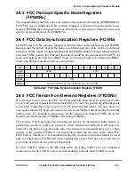
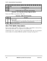
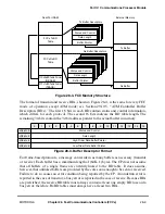
Some parameters in Table 28-5 are not described and are listed only to provide information
for experienced users and for debugging. The user need not access these parameters in
normal operation.
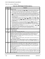
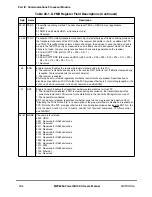
Table 28-5. FCC Parameter RAM Common to All Protocols
Offset
1
Name
Width
Description
0x00
RIPTR
Hword Receive internal temporary data pointer. Used by microcode as a temporary buffer for
data. Must be 32-byte aligned and the size of the internal buffer must be 32 bytes unless
it is stated otherwise in the protocol speciÞcation. For best performance, it should be
located in the following address ranges: 0x3000Ð0x4000 or 0xB000Ð0xC000.
0x02
TIPTR
Hword Transmit internal temporary data pointer. Used by microcode as a temporary buffer for
data. Must be 32-byte aligned and the size of the internal buffer must be 32 bytes unless
it is stated otherwise in the protocol speciÞcation. For best performance it should be
located in the following address ranges: 0x3000Ð0x4000 or 0xB000Ð0xC000.
0x04
Ñ
Hword Reserved, should be cleared.
0x06
MRBLR
Hword Maximum receive buffer length (a multiple of 32 for all modes). The number of bytes that
the FCC receiver writes to a receive buffer before moving to the next buffer. The receiver
can write fewer bytes to the buffer than MRBLR if a condition such as an error or end-of-
frame occurs, but it never exceeds the MRBLR value. Therefore, user-supplied buffers
should be at least as large as the MRBLR.
Note that FCC transmit buffers can have varying lengths by programming TxBD[Data
Length], as needed, and are not affected by the value in MRBLR.
MRBLR is not intended to be changed dynamically while an FCC is operating. Change
MRBLR only when the FCC receiver is disabled.
0x08
RSTATE
Word
Receive internal state. The high byte, RSTATE[0Ð7], contains the function code register;
see Section 28.7.1, ÒFCC Function Code Registers (FCRx).Ó RSTATE[8Ð31] is used by
the CP and must be cleared initially.
Summary of Contents for MPC8260 PowerQUICC II
Page 1: ...MPC8260UM D 4 1999 Rev 0 MPC8260 PowerQUICC II UserÕs Manual ª ª ...
Page 66: ...lxvi MPC8260 PowerQUICC II UserÕs Manual MOTOROLA ...
Page 88: ...1 18 MPC8260 PowerQUICC II UserÕs Manual MOTOROLA Part I Overview ...
Page 120: ...2 32 MPC8260 PowerQUICC II UserÕs Manual MOTOROLA Part I Overview ...
Page 138: ...Part II iv MPC8260 PowerQUICC II UserÕs Manual MOTOROLA Part II Configuration and Reset ...
Page 184: ...4 46 MPC8260 PowerQUICC II UserÕs Manual MOTOROLA Part II ConÞguration and Reset ...
Page 202: ...Part III vi MPC8260 PowerQUICC II UserÕs Manual MOTOROLA Part III The Hardware Interface ...
Page 266: ...8 34 MPC8260 PowerQUICC II UserÕs Manual MOTOROLA Part III The Hardware Interface ...
Page 382: ...10 106 MPC8260 PowerQUICC II UserÕs Manual MOTOROLA Part III The Hardware Interface ...
Page 392: ...11 10 MPC8260 PowerQUICC II UserÕs Manual MOTOROLA Part III The Hardware Interface ...
Page 430: ...Part IV viii MOTOROLA Part IV Communications Processor Module ...
Page 490: ...14 36 MPC8260 PowerQUICC II UserÕs Manual MOTOROLA Part IV Communications Processor Module ...
Page 524: ...17 10 MPC8260 PowerQUICC II UserÕs Manual MOTOROLA Part IV Communications Processor Module ...
Page 556: ...18 32 MPC8260 PowerQUICC II UserÕs Manual MOTOROLA Part IV Communications Processor Module ...
Page 584: ...19 28 MPC8260 PowerQUICC II UserÕs Manual MOTOROLA Part IV Communications Processor Module ...
Page 632: ...21 24 MPC8260 PowerQUICC II UserÕs Manual MOTOROLA Part IV Communications Processor Module ...
Page 652: ...22 20 MPC8260 PowerQUICC II UserÕs Manual MOTOROLA Part IV Communications Processor Module ...
Page 668: ...23 16 MPC8260 PowerQUICC II UserÕs Manual MOTOROLA Part IV Communications Processor Module ...
Page 758: ...27 28 MPC8260 PowerQUICC II UserÕs Manual MOTOROLA Part IV Communications Processor Module ...
Page 780: ...28 22 MPC8260 PowerQUICC II UserÕs Manual MOTOROLA Part IV Communications Processor Module ...
Page 874: ...29 94 MPC8260 PowerQUICC II UserÕs Manual MOTOROLA Part IV Communications Processor Module ...
Page 920: ...31 18 MPC8260 PowerQUICC II UserÕs Manual MOTOROLA Part IV Communications Processor Module ...
Page 980: ...A 4 MPC8260 PowerQUICC II UserÕs Manual MOTOROLA Appendixes ...
Page 1002: ...Index 22 MPC8260 PowerQUICC II UserÕs Manual MOTOROLA INDEX ...
Page 1006: ......

